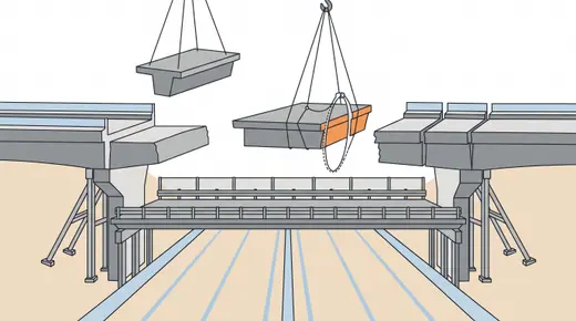
About bridge · Construction methods

How bridges get built

162 methods in 13 families, from the first borehole to the last bearing: investigation, ground improvement, foundations and piling, piers and pylons, cast-in-place, precast and steel decks, cable-supported and arch erection, heavy lift and accelerated construction, finishing and maintenance. One page per method: what it is, how it is done, where it fits, what it costs, what goes wrong.

Search by name or by what you are trying to do, or pick a family. Methods marked "in the game" are the ones Bridge Master lets you choose and judges by the same rules printed on their pages.

Site investigation and testing 15Ground improvement 11Shallow foundations, cofferdams and dewatering 10Driven piles 15Bored piles and deep foundations 12Caissons and marine foundations 12Piers, pylons and abutments 11Cast-in-place concrete decks 10Precast concrete decks 14Steel erection 8Cable-supported and arch bridges 14Heavy lift, moving and accelerated construction 12Finishing, articulation and maintenance 18

Site investigation and testing

Nothing in a bridge is decided before the ground is known. These are the methods that turn a site into numbers: what to drill, what to test, and how to prove a foundation before the bridge sits on it.
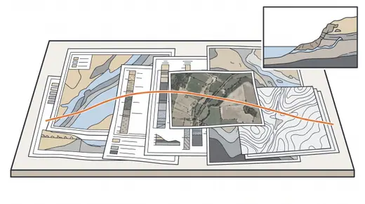
Desk study and walkover surveyThe first and cheapest stage of any investigation: geological maps, old boreholes, aerial photographs, flood and scour records, utility drawings and a walk along the alignment. It sets the borehole layout and often changes it.
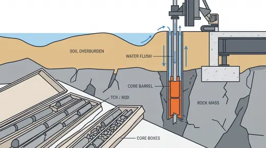
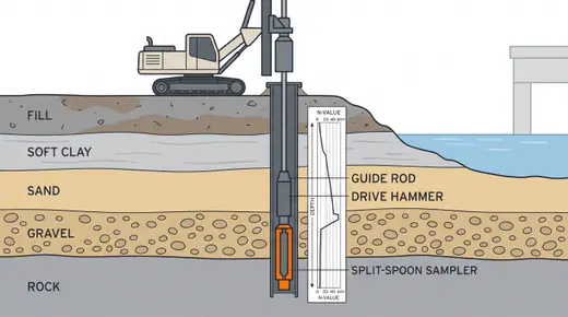
Boreholes with SPT and samplingThe backbone of bridge ground investigation: a borehole at every pier and abutment, logged metre by metre, with the standard penetration test giving an N-value every 1.5 m and samples for the laboratory. Rock is cored and its quality logged (RQD).
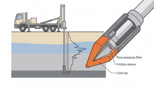
Cone penetration testing (CPT and CPTu)A cone pushed into the ground at 20 mm per second, measuring tip resistance, sleeve friction and pore pressure continuously. It profiles soft soils far better than boreholes and gives pile capacity directly through empirical methods.
Rock coring and rock mass loggingWhere piles will socket into rock, the rock is cored with diamond bits and logged for strength, fracturing and weathering. The socket design lives or dies on these logs.
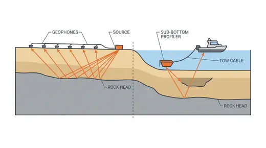
Geophysical surveysNon-intrusive surveys that fill the gaps between boreholes: rock head profile, buried channels, cavities and soft pockets. They do not replace boreholes but they say where to put them.
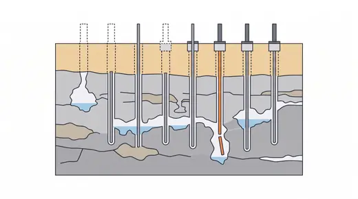
Karst and cavity probingIn limestone and other soluble rock, every pile can meet a void. Probing below each foundation location, and often below each pile, finds cavities before the drilling rig does.
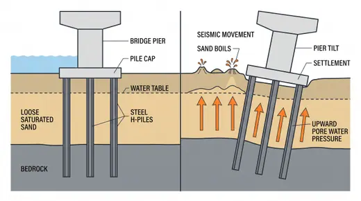
Liquefaction assessmentLoose saturated sands and silts can lose strength in an earthquake. The assessment compares the cyclic stress the design earthquake imposes with the cyclic resistance inferred from SPT or CPT, and tells you whether piles must be designed for lateral spreading and downdrag.
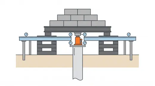
Static pile load testThe definitive proof of a pile: load a test pile in steps to 1.5-2.5 times its working load and measure settlement. Everything else is an estimate; this is a measurement.
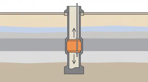
Bi-directional (Osterberg cell) load testA hydraulic jack cast into the pile pushes the upper part of the shaft up against the lower part and base. No kentledge, no reaction piles, and loads far beyond what a surface test can reach: the standard proof for large bored piles and barrettes.
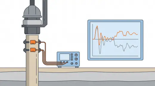
Dynamic load testing (PDA) and signal matchingStrain and acceleration transducers on the pile head record the wave from a hammer blow; signal matching turns the record into an estimated capacity and its split between shaft and base. Fast, cheap and done on many piles, but an estimate that should be tied to a static test.
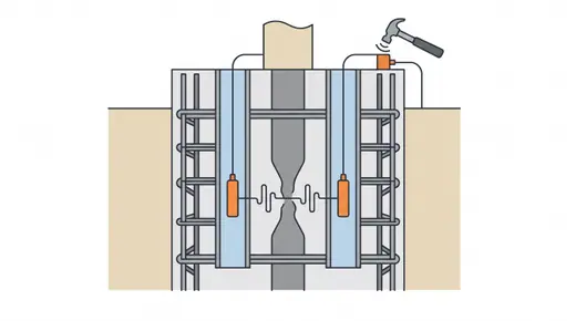
Pile integrity testing (sonic echo and cross-hole sonic logging)Tests that look for defects rather than capacity: necking, voids, soil inclusions and poor concrete in bored piles. Sonic echo taps the head; cross-hole sonic logging sends pulses between tubes cast into the pile; thermal profiling reads the heat of hydration.
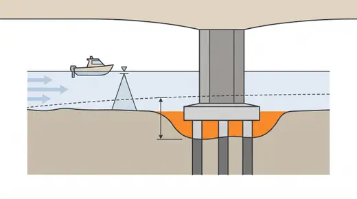
Scour investigation and hydraulic studyBefore a pier goes into a river, the river is measured: discharge, velocity, bed material, historic bed changes and the scour that the design flood will cause at each pier and at the contracted waterway. More bridges fail by scour than by any structural cause.
Instrumentation and monitoring during constructionMeasurement during the works: settlement plates under embankments, piezometers in soft clay, inclinometers behind excavations, strain and deflection on cantilevers and stays. It turns assumptions into data while there is still time to act.In-situ testing: pressuremeter, dilatometer, vane and plate load testsTests that measure stiffness and strength in place, where sampling would disturb the ground: the pressuremeter expands a probe in a borehole, the flat dilatometer pushes a blade and inflates a membrane, the vane shears soft clay, and the plate load test loads the surface. They supply the moduli and undrained strengths that SPT and CPT correlations can only estimate.Over-water site investigation from jack-ups, barges and vesselsBoreholes, CPTs and geophysics for piers in rivers, estuaries and the sea, carried out from a jack-up, spud barge, anchored pontoon or drilling vessel. The platform, the weather and the positioning govern cost and quality as much as the drilling itself.

Ground improvement

When the ground is too soft, too loose or too wet for what the bridge and its approaches need, it is treated rather than replaced. These methods make soft clay consolidate faster, densify loose sand, mix cement into mud, or bypass the problem with light fill and piles.
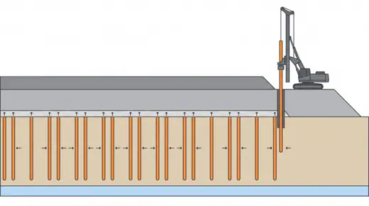
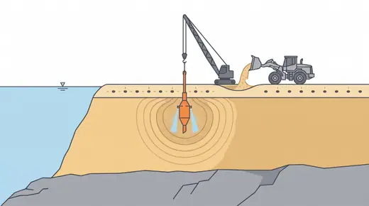
Prefabricated vertical drains with surchargePlastic drains pushed through soft clay at 1-2 m spacing shorten the drainage path from metres to decimetres, so a surcharge embankment consolidates the clay in months instead of decades. The standard treatment for bridge approaches on soft estuarine and coastal clays.
Stone columns (vibro-replacement)A vibrating probe forms a hole that is backfilled with compacted gravel in lifts, leaving a stiff column 0.6-1.2 m in diameter. Columns share the load, speed drainage and reduce liquefaction in loose sand and soft-to-firm clay.
Vibro-compactionA vibroflot penetrates loose clean sand and densifies it by vibration and water jetting, with sand added at the surface as the ground settles. It is the cheapest cure for loose reclaimed sand and the standard treatment against liquefaction in it.
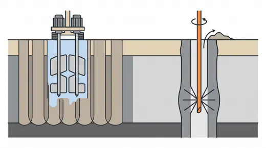
Deep cement mixing (DCM) and jet groutingCement is mixed into the soil in place, either mechanically with rotating paddles (DCM) or by high-pressure jets (jet grouting), forming columns or blocks with strengths of 0.5-5 MPa. It stiffens soft clay under abutments, makes cofferdam plugs and seals excavation bases.
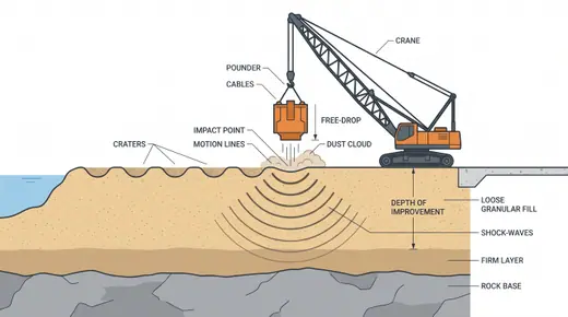
Dynamic compactionA 10-25 t weight dropped from 15-25 m on a grid densifies loose granular fill and rubble to 8-12 m. Crude, fast and cheap where there is space and no neighbours.
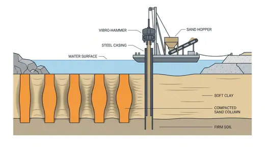
Sand compaction pilesA steel casing is vibrated into the ground, sand is fed and compacted by repeated withdrawal and re-driving, leaving dense sand columns about 0.7 m in diameter on land and up to about 2 m offshore that improve soft clay and loose sand. A Japanese and Korean standard for port and coastal works.
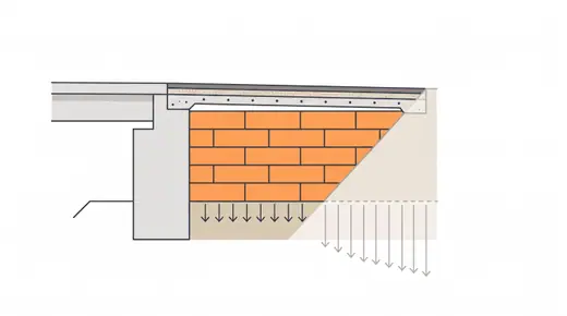
Lightweight fill (EPS geofoam, foamed concrete, LWA)Instead of loading soft clay with a heavy embankment, the approach is built of material that weighs almost nothing: expanded polystyrene blocks at 20-30 kg/m3, foamed concrete at 400-800 kg/m3 or lightweight aggregate. Settlement and lateral load on the abutment shrink accordingly.
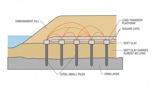
Piled embankment with load-transfer platformA grid of piles or columns with small caps, a geogrid-reinforced granular platform on top, and the embankment above. The fill arches onto the caps and the soft clay is bypassed: no waiting for consolidation, no long-term settlement at the abutment.
Scour protection: riprap, mattresses and collarsWhere the scour depth cannot be designed out, the bed around the pier is armoured. Riprap sized to the design velocity, concrete mattresses, or collars and sacrificial piles that break up the horseshoe vortex.Vacuum consolidation (vacuum preloading)Instead of piling fill on soft clay, a vacuum is applied through vertical drains beneath an airtight membrane or through capped drains, so that atmospheric pressure consolidates the clay as if it carried 3–4 m of fill. It is used alone or with fill where fill is scarce, staged loading would be unstable, or neighbours must not be pushed outward.Permeation, compaction and compensation groutingGrout is injected into the ground without excavating it: thin grouts permeate sands and gravels to seal and strengthen them, stiff mortar displaces and densifies loose soil, and controlled fracture grouting lifts structures or offsets settlement as it happens. On bridges it seals cofferdams and excavations, fills karst and mine voids, and underpins or re-levels existing foundations.

Shallow foundations, cofferdams and dewatering

Where good ground is near the surface, a footing is cheaper than any pile. Getting to that ground dry, especially in a river, is the real work: cofferdams hold the water back, dewatering keeps the excavation workable, and a concrete seal stops the bottom from blowing.
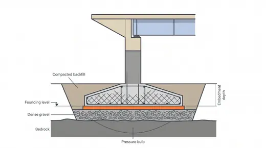
Spread footing on soil or rockA reinforced concrete pad wide enough that the bearing pressure stays below what the ground can carry, and deep enough to be below frost, scour and softened surface layers. On rock, the pad is keyed or dowelled into a cleaned, sound surface. The first foundation an engineer should try and the one most often rejected too early.
Mat (raft) foundationOne large slab under a group of columns or a wide pier, spreading the load over ground that would fail under individual pads. Used under multi-column bents, portal frames and pylon bases where the loads are close together.Dewatering: sumps, wellpoints and deep wellsKeeping an excavation dry below the water table. Sumps and pumps for small inflows in clay and rock; wellpoints for sands to about 5-6 m of drawdown per stage; deep wells with submersible pumps for larger drawdowns. Uncontrolled water is the fastest way to lose a footing excavation.
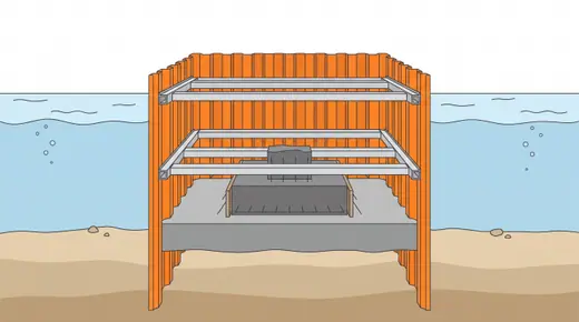
Sheet-pile cofferdamInterlocking steel sheet piles driven around the foundation, braced with walings and struts as the water is pumped out, giving a dry box to build a footing or pile cap in a river up to about 8-10 m deep. The workhorse of river pier construction.
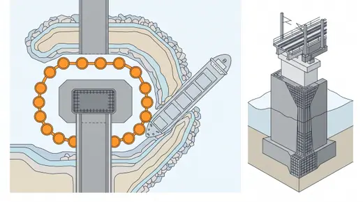
Double-wall and cellular cofferdamsTwo rings of sheet piles with sand or gravel fill between them, or a chain of filled circular cells, stand as gravity structures against 10-20 m of water without internal bracing. They are the cofferdam of choice for large pier footprints in deep, fast water.
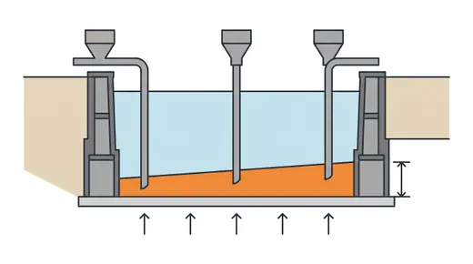
Tremie concrete sealA mass of concrete placed underwater through a tremie pipe on the base of a cofferdam, thick enough that its weight plus friction on the sheet piles resists the uplift when the cofferdam is pumped dry. It converts a wet hole into a dry working floor.
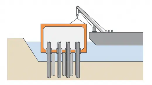
Precast and floating cofferdam boxesInstead of driving sheet piles, a steel or precast concrete box is floated to the pier, lowered onto pre-installed piles or the bed, and pumped dry. It doubles as the permanent pile-cap formwork and removes divers and cofferdam bracing from the critical path.
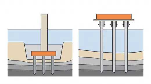
Pile caps in waterThe block that gathers a pile group into one pier. On land it is a footing in an excavation; in water there are two choices: a low cap cast below the bed inside a cofferdam, protected from scour and ship impact, or a high cap at or above water level cast in a suspended form, faster and cheaper but exposed.
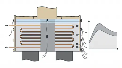
Mass concrete and thermal controlFootings, caps and pylon bases are thick enough that the heat of hydration cannot escape; the core can reach 70 C while the surface cools, and the difference cracks the concrete. Thermal control is part of building a foundation, not an optional extra.
Secant-pile and diaphragm-wall cofferdamsA watertight ring or box of interlocking bored piles or diaphragm-wall panels, built from ground level before any excavation, then propped or shaped as a ring so the inside can be dug deep and nearly dry. It is used where sheet piles cannot be driven, cannot reach a cut-off or would move too much: river banks, road and rail corridors, and the deep anchorages of suspension bridges.

Driven piles

A pile that is hammered, vibrated or pressed into the ground displaces the soil rather than removing it. Driven piles are fast, their quality is visible blow by blow, and the ground around them is densified; the price is noise, vibration, and refusal when they meet something hard.
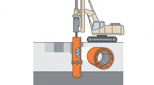
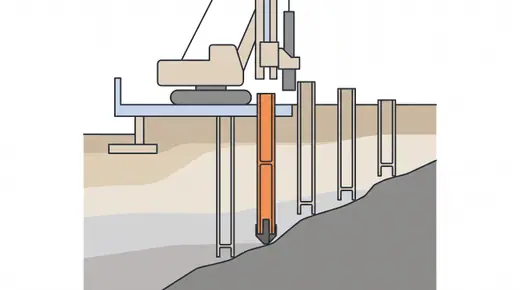
PHC spun concrete pilesHollow prestressed concrete piles spun in a factory at 80 MPa or more, 350-1,200 mm in diameter, delivered in 10-15 m lengths and jointed with welded end plates. The economical pile of Korea, Japan, China and Southeast Asia wherever a dense sand or gravel layer sits within 10-40 m.
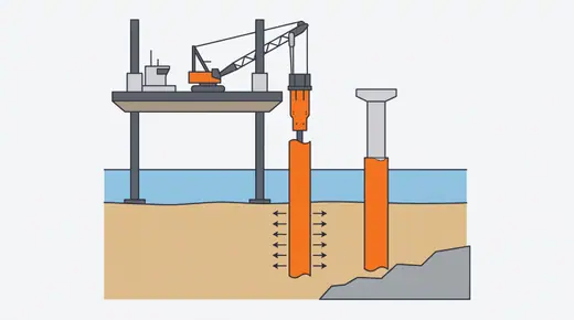
Prestressed concrete square pilesSolid square prestressed piles 300-900 mm on a side, cast in long-line beds and driven in single lengths up to 30-40 m, typical of US Gulf Coast, Florida and Southeast Asian practice. Robust in driving, good in marine exposure with adequate cover, and easy to make on site for large projects.Steel pipe piles (open- and closed-ended)Steel tubes 400-2,500 mm in diameter, driven open-ended (the soil plug carries part of the base) or closed with a shoe (full displacement), spliced by welding to any length. High bending capacity, ideal in water, for scour and ship impact, and for liquefaction; the standard marine pile of Japan and Korea.
Steel H-pilesRolled H-sections driven as low-displacement piles, threading through dense layers and gravels that stop other piles, and driving to point bearing on rock. Common in North America and Europe for abutments and integral bridges.
Timber pilesThe oldest pile: a tree trunk driven tip-first, usually treated against decay. Light, cheap, and adequate for small bridges and temporary trestles in soft ground where loads are modest and the piles stay below the water table.
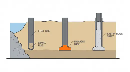
Driven cast-in-situ pilesA steel tube with a closed shoe or a gravel plug is driven, then withdrawn while concrete is placed, leaving a displacement pile with an enlarged base (Franki) or a straight shaft. The bearing capacity of a driven pile with the flexibility of casting the length to suit the ground.
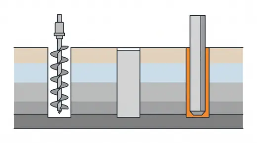
SIP and pre-bored driven pilesA hole is augered slightly larger than the pile and filled with cement slurry; the precast pile is lowered and lightly driven or pressed into it. It gives a driven pile's simplicity without the noise and vibration, at the price of lower shaft friction and a wait for the slurry.
Rotary screw (helical) pilesA steel pipe with a helical tip is screwed into the ground by a rotary head, with no spoil and little noise. In Japan it is a full displacement pile for medium loads; elsewhere helical anchors carry lighter structures and temporary works.
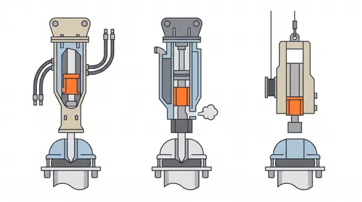
Impact hammers: hydraulic, diesel and dropThe hammer decides whether a pile reaches depth and arrives undamaged. Hydraulic hammers give controllable energy and are the modern default; diesel hammers are simple and powerful but smoky and less controllable; drop hammers survive on small jobs and for driven cast-in-situ piles.
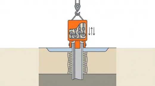
Vibratory drivingEccentric weights vibrate the pile at 20-40 Hz, liquefying the soil around it so the pile sinks under its own weight and the hammer's. Fast and quiet in sands, ideal for sheet piles, casings and steel pipes, but it does not prove bearing capacity, so the last metres are usually impact-driven.
Press-in (silent) pilingA hydraulic machine grips piles already installed and uses their resistance to push the next one in, silently and without vibration. Born for sheet piles in Japanese cities, now used for tubular piles and for widening bridges next to live traffic and housing.Driving control: sets, refusal, restrike and splicingThe rules that decide when a driven pile is done: the set (penetration per blow) that corresponds to the required capacity, the refusal limit that protects the pile, and the restrike that reveals setup in clay or relaxation in dense sand. Getting them wrong wastes piles or leaves capacity on paper.Corrosion protection of steel pilesSteel in the sea loses 0.1-0.3 mm a year in the splash and tidal zones, more with chlorides and pollution. Piles are protected by extra thickness, coatings, concrete jackets and cathodic protection so the bridge outlives its design life.Raked (battered) pile groupsPiles driven at an inclination, typically 1 horizontal to 3-8 vertical, so that horizontal loads from ships, waves, current, braking or earth pressure are carried mainly as axial force rather than bending. They are standard for marine piers, dolphins, abutments and high caps on driven piles, but are restricted in strong earthquake zones and in ground that will settle.Jetting and predrilling to aid drivingWater jets or a predrilled hole loosen or remove dense upper soil so a displacement pile can reach depth without excessive driving stress, after which the final metres are driven to the set. It is common for concrete piles in dense sand and for passing hard crusts and obstructions, at the price of reduced shaft friction and lateral support in the jetted or drilled zone.

Bored piles and deep foundations

When the ground is removed and replaced with concrete rather than displaced, the pile can be as large as the rig can drill and can be socketed into rock. Bored piles carry the heaviest bridge loads, tolerate boulders and city limits on noise, and demand the most from supervision because nobody sees the pile until it is tested.
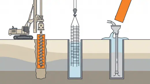
Drilled shafts (bored piles) with casing or slurryA hole 0.8-3 m in diameter is drilled with a rotary rig, held open by a temporary casing or by bentonite or polymer slurry, then a cage is lowered and concrete placed by tremie. The universal heavy-load bridge foundation: pylons, river piers, urban viaducts, anything into rock.
Full-length casing with oscillator or rotatorA steel casing is twisted into the ground segment by segment by a hydraulic oscillator or rotator, and the soil is grabbed out from inside with a hammer grab. The hole is fully supported at all times, so boulders, running sand and old foundations are handled without slurry.
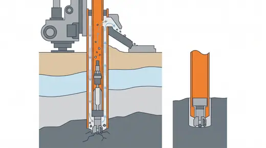
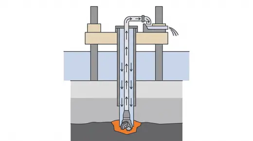
Reverse circulation drilling (RCD)A rotating drill bit at the bottom of a hollow drill string cuts the ground while water or slurry is pumped up through the string carrying the cuttings out. It drills 1.5-3.5 m holes to 100 m or more, through rock, and is the pile of choice for pylon foundations built from jack-ups and platforms at sea.
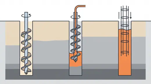
Continuous flight auger (CFA) pilesA hollow-stem auger is screwed to full depth in one pass and concrete is pumped through the stem as it is withdrawn, then a cage is pushed into the fresh concrete. No casing, no slurry, very fast, moderately quiet; the mass-production pile of European and North American viaducts on soil.
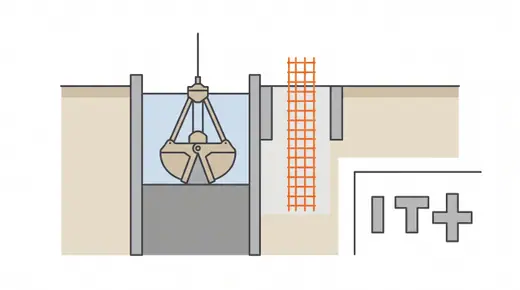
Barrettes and diaphragm-wall foundationsA rectangular pile excavated with a diaphragm-wall grab or hydromill under bentonite, typically 0.8-1.5 m by 2.8-7 m, giving very high axial and bending capacity in one element. Used under pylons and tall piers where round shafts would be too many or too large.
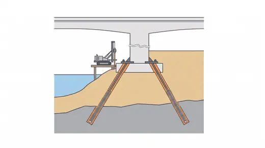
MicropilesSmall-diameter (150-300 mm) drilled piles with a central steel bar or tube grouted under pressure, installed with rigs that fit under an existing bridge. Individually modest (300-1,500 kN) but installed in numbers, they underpin, retrofit and reach into rock where large rigs cannot go.
Percussion rotary drilled (PRD) steel pipe pilesA down-the-hole hammer inside a steel pipe advances the pipe through soil and into rock; the socket is then cleaned, a cage lowered and the pipe filled with concrete. It gives a driven pile's steel section with a bored pile's rock socket, quietly, in a small footprint: a Korean answer to shallow weathered rock, boulders and city sites.
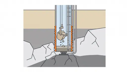
Rock sockets and base treatmentThe part of a bored pile that carries the load into rock. Socket length, roughness and cleanliness decide the capacity; base and shaft grouting can double what a poorly cleaned socket would give.
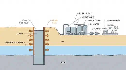
Bentonite and polymer slurry stabilisationThe fluid that keeps a bored hole open: bentonite forms a filter cake on the wall and holds the ground by hydrostatic pressure; polymer slurries do the same with less mud, easier disposal and better concrete bond. Managing the slurry is managing the pile.
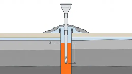
Tremie concreting of pilesConcrete for a bored pile is placed through a pipe whose tip stays embedded in the fresh concrete, so the mix displaces the slurry without mixing with it. The mix must flow for hours without segregating; the pour must not stop.
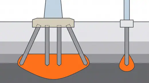
Pile groups, caps and group effectsPiles under a pier act as a group: closer than about 2.5-3 diameters they share soil and lose efficiency in friction, while a group settles more than a single pile because the stress bulb is deeper. The cap must spread the pier load to every pile, and a raked outer pile row helps with lateral load.
Base and shaft post-grouting of bored pilesCement grout is injected under pressure through circuits cast into a bored pile, at the toe and sometimes along the shaft, after the concrete has set. It compacts debris and loose soil under the base, pre-loads the toe and densifies the ground around the shaft, so the pile mobilises end bearing at small settlement and pile-to-pile scatter falls.

Caissons and marine foundations

Deep water, deep scour, ships, ice and earthquakes call for foundations that are structures in their own right: wells sunk through the bed, boxes floated into place, single giant piles, and the platforms that let people work over water at all.
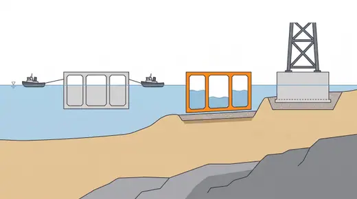
Open caisson (well foundation)A concrete or steel shell with a cutting edge, built up in lifts on the bed or on a sand island and sunk under its own weight while the soil inside is dredged out. It ends as a massive block founded far below scour depth: the traditional foundation of large river bridges in India, China and the Mississippi, still unmatched for deep scour and ship impact.
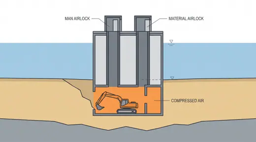
Pneumatic caissonAn open caisson with a sealed working chamber at the bottom kept dry by compressed air, so workers (now often remote-controlled excavators) dig in the dry through boulders and onto rock. Precise founding, no tilt surprises, and historically dangerous; modern Japanese practice uses unmanned excavation and pressures beyond 0.3 MPa with mixed-gas decompression.
Floating (box) caissonA concrete or steel box built in a dry dock, towed to the pier, ballasted down onto a prepared bed or a pile group, and filled. It moves the foundation work into a yard and leaves only the seating to the sea: the pylon foundation of choice for straits where dredging or piling in place is slow.
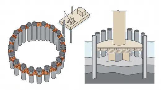
Steel pipe sheet pile (SPSP) well foundationInterlocking steel pipe piles are driven in a ring; the interlocks are grouted so the ring works as a rigid well, and a top slab ties it together. The ring is first the cofferdam and then the permanent foundation: a Japanese method that cut river and coastal pier construction time dramatically.
Large-diameter monopilesOne steel tube 3-6 m in diameter, driven or drilled to 40-70 m, carries a pier alone, borrowed from offshore wind. It removes the cap and the group: one pile, one pier, one lift. In bridge work it suits sea viaducts with many identical piers in sand.
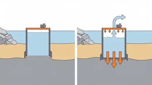
Suction caissonsAn open-bottomed steel cylinder lowered onto the seabed and sucked in by pumping water out of the top, so the pressure difference drives it into clay or sand without a hammer. Quiet, reversible, and quick in the right soils; used for anchors, offshore jackets and increasingly for temporary and light bridge foundations.
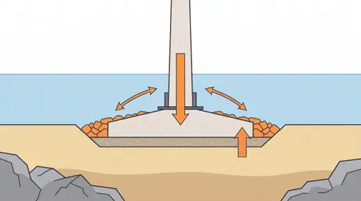
Gravity base foundationsA large concrete base that resists sliding and overturning by its own weight, placed on a prepared gravel bed on rock or dense sand. For pylons in straits with good seabeds it is the simplest foundation there is, provided the bed can be prepared and the base delivered.
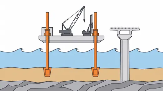
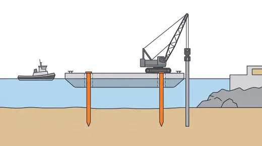
Jack-up platformsA barge with legs that are lowered to the seabed and then jack the hull above the waves, giving a steady drilling or piling deck in 5-40 m of water. Weather-independent once elevated, it is the platform behind most bored pile work at sea.
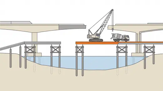
Temporary trestles and access bridgesA steel-piled bridge for cranes and trucks built out over shallow water alongside the alignment, so the permanent piers can be built with land plant. It costs a bridge of its own but removes barges, tides and weather from the pier works.
Floating barges and spud bargesA flat-top barge with a crane, held by spuds (vertical legs dropped into the bed) or anchors. The cheapest way to put a rig or crane over water, and the most weather-sensitive: it moves with the waves and the tide, so precision work waits for calm.
Artificial islands for marine foundations (sand, rock-bund and cellular islands)An island of sand or rock is built in the water, held by slopes, rock bunds, sheet-pile cells or large steel cylinders, so that foundations can be built with land methods or a bridge can hand over to a tunnel. Temporary islands let caissons be sunk and piles be drilled in shallow rivers; permanent islands carry tunnel portals and can shield piers from ships.Steel jacket foundations on pilesA prefabricated tubular steel space frame (the jacket) is set on the seabed and fixed by steel piles driven through its legs or through sleeves at its base, then grouted. Borrowed from offshore oil and wind, it moves most of the work into a fabrication yard and gives a stiff, light foundation in deep or soft water, and it has been used for marine bridges and pile-supported airport structures.

Piers, pylons and abutments

Between foundation and deck stands the substructure. How a pier is formed decides how fast a viaduct rises, how a 200 m pylon stays plumb, and whether an abutment moves with the deck or fights it.
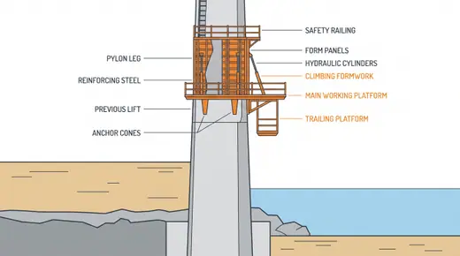
Cast-in-place piers with formwork liftsThe ordinary way to build a pier: steel or timber formwork panels are set on the footing, concrete is poured in lifts of 3-6 m, the panels are stripped and lifted to the next lift by crane. Cheap, flexible and slow when the pier is tall.
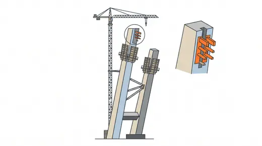
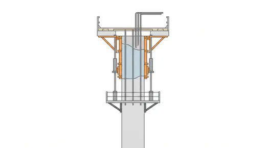
Climbing and jump formworkFormwork that lifts itself on the pier it has just cast, anchored into the previous lift, with working platforms attached. Crane-climbed systems move with a crane; self-climbing systems use hydraulic rams and free the crane entirely. The method for tall piers and every concrete pylon.
SlipformA short form (1-1.2 m) is raised continuously by jacks on climbing rods while concrete is poured around the clock; the pier grows 3-6 m per day with no lift joints. Fast for constant sections, unforgiving of stops.
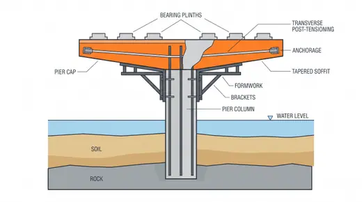
Pier heads, hammerheads and pier capsThe widened top of a pier that carries the bearings. A hammerhead cantilevers out on both sides and is cast on brackets or a shored platform; a cap on a multi-column bent spans between columns on falsework. Post-tensioning is common in wide hammerheads.
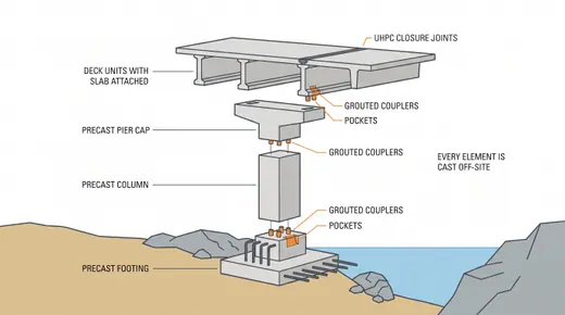
Precast segmental piers and capsPiers and caps cast in a yard as segments or complete units, stacked on site in hours and connected with grouted couplers, post-tensioning or grouted sleeves. Removes formwork, curing and scaffold from the site: the substructure half of accelerated bridge construction.in the game
Pylon construction: concrete, anchorage zones and geometryA pylon is a tall pier with a cable anchorage zone at the top: the concrete legs climb with jump forms, the cross beams are cast on brackets or lifted as steel, and the stay anchorages are steel boxes or corrugated pipes embedded in a congested, heavily post-tensioned zone. Geometry control is the whole game: the pylon must be where the cables expect it.
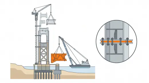
Steel and composite pylonsPylons fabricated as steel boxes in sections of 10-20 m, lifted by tower or floating cranes and bolted or welded, sometimes over a concrete lower part. Faster than concrete above the deck, lighter on the foundation, and dependent on lifting capacity and fabrication precision.
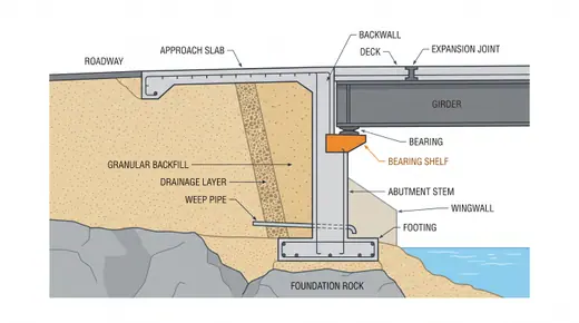
Seat-type and cantilever abutmentsA concrete wall with a bearing shelf, retaining the approach fill and carrying the end of the deck on bearings, with an expansion joint between deck and backwall. The conventional abutment; simple to build, and the place where most bridge maintenance happens (joints, bearings, approach slabs).
MSE (reinforced soil) abutmentsThe approach fill itself is turned into a wall with layers of steel strips or geogrid behind precast facing panels, and the deck sits on a small seat on top or on piles through the fill. Cheaper and faster than a concrete wall, tolerant of settlement, and the standard in the game and in most highway practice for fills up to about 12-15 m.Integral and semi-integral abutmentsThe deck is cast into the abutment so there is no expansion joint and no bearing at the ends; the abutment moves with the deck on flexible piles or a sliding sleeper. No joint means no leak, no bearing replacement and lower whole-life cost: the game rewards it in the upkeep score.
Pier protection: fenders, dolphins and collision wallsA pier in a navigation route or beside a railway is protected from what can hit it: rubber fenders and floating fenders absorb ship energy, independent dolphins and artificial islands stop the ship before the pier, and a crash wall shields rail-side piers from derailed trains.

Cast-in-place concrete decks

Concrete poured where the bridge will stand: on falsework from the ground, in a travelling scaffold, from the piers outward as balanced cantilevers, or on a casting bed behind the abutment and pushed out. Each way trades formwork cost against span, height and access.
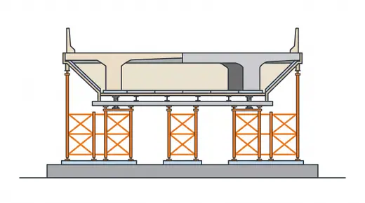
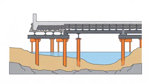
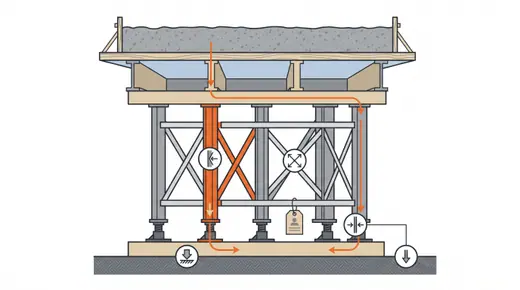
Full staging method (ground falsework)Formwork supported on scaffold towers or a timber and steel falsework grid built up from the ground; the deck is cast in place span by span or all at once. Cheapest for short bridges over dry, firm ground with no traffic below, and the origin of every other cast-in-place method.in the game
Falsework on temporary piles (shallow water)Cast-in-place on falsework carried by temporary steel piles driven into the riverbed, so the method survives 1-3 m of slow water outside the flood season. The classic construction of small river and canal bridges before precast girders took over.in the game
Movable scaffolding system (MSS)A self-launching steel truss or girder that carries the complete formwork for one span, casts it, lowers the forms and rolls to the next pier. Overhead and underslung types exist; both remove the ground from the equation, so long viaducts over water, roads and soft ground can be cast in place at one span every 7-14 days.in the gameBalanced cantilever, cast in place (form travellers)From each pier, the box girder grows outward in 3-5 m segments cast in a pair of form travellers, one on each side to keep the pier balanced, until the cantilevers from adjacent piers meet at midspan and are joined by a closure pour. The method for 80-250 m concrete spans over rivers, valleys and railways where nothing can stand below.in the gameIncremental launching (ILM)The deck is cast in 15-30 m segments on a fixed casting bed behind the abutment and pushed out over the piers with hydraulic jacks, a steel launching nose ahead of it reducing the cantilever moment. All the work happens in one place at ground level; the deck arrives at the far abutment span by span.in the gameIncremental launching with temporary piersLaunching as usual, but temporary steel piers halve the launching span so 70-110 m permanent spans can be launched with a normal box depth. The method for valleys and rivers too deep for falsework but shallow enough for a few temporary bents.in the gameCast-in-place post-tensioned box and slab decksThe deck types most cast-in-place methods produce: post-tensioned box girders for spans of 40-250 m and solid or voided slabs for short spans. Post-tensioning is what makes the span; the ducts, tendons, anchorages and grouting are the critical trade.Form travellers and traveller anchorageThe moving formwork of balanced cantilever construction: a steel frame anchored to the last segment carries the soffit, web and top forms for the next one, then rolls forward. Its anchorage is the most safety-critical bolt group on the site.
Falsework and temporary works engineeringEvery cast-in-place method relies on a temporary structure that carries the wet concrete, the crew and the plant. Falsework has killed more construction workers than any permanent structure; the procedures that prevent it are as much a method as any formwork.
Concrete arch on centering and the Melan (stiff skeleton) methodA concrete arch rib is cast in place, or assembled from precast voussoirs, on a temporary centering that carries it until the crown is closed and the arch can stand; the centering is then lowered and reused or removed. In the Melan or stiff-skeleton variant a light steel arch is erected first, carries the formwork and the wet concrete in stages, and stays embedded in the rib.

Precast concrete decks

Concrete cast in a yard under a roof, then carried to the bridge. Precasting trades site work for logistics: girders by the truckload, segments by the barge, whole spans by the carrier. It is fast, repeatable and quality-controlled, and it stands or falls on the erection equipment.
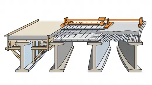
Crane erection of precast girdersPrecast I, U or bulb-T girders are lifted from the truck onto the pier caps by one or two mobile or crawler cranes standing beside the bridge, then a deck slab is cast on top. The most common bridge construction on earth for spans of 20-45 m wherever a crane can stand.in the gameLaunching girder (beam launcher) for precast girdersA steel truss spanning two piers ahead of the completed deck, with trolleys that pick each precast girder from the deck behind and place it on the next span. It erects girders where no crane can stand: over water, rail, roads and steep ground, at one span per one to three days.in the gameSpliced precast girders on temporary towersPrecast girder segments too long to transport in one piece (up to 60-90 m spans) are erected on temporary towers or a strongback, spliced with cast-in-place joints, and post-tensioned through the whole length. It stretches precast girders to spans that used to need cast-in-place boxes.in the gameSpan-by-span precast segmental with gantryAll the match-cast segments of one span (2.5-3.5 m each) are hung from an overhead or underslung gantry, glued with epoxy, and post-tensioned into a span in two to four days. The fastest viaduct method ever built and the standard for metros, expressways and long approach viaducts.in the gameBalanced cantilever with precast segmentsMatch-cast segments are lifted from barges or trucks by a deck-mounted lifting frame, a crane or a launching gantry, glued and stressed symmetrically from each pier, two to four segments a day per pier. The fast way to build 60-150 m spans in quantity.in the gameFull-span precast erection (high-speed rail type)Complete 25-40 m box spans of 600-900 t are cast in a yard, carried along the finished deck by a rubber-tyred carrier and set on the next pier pair by a launching gantry. One span per shift and kilometres per year: the viaduct method of Chinese, Taiwanese and Korean high-speed rail.in the gameSegment casting: short-line and long-line match castingPrecast segmental bridges are only as good as the yard. Match casting pours each segment against the previous one so the joints fit perfectly; short-line does it in a fixed cell with the previous segment moved into position, long-line casts a whole cantilever on a long bed. Geometry control in the yard decides the geometry of the bridge.Epoxy and dry joints, shear keys and temporary PTThe joint between match-cast segments: a thin epoxy layer squeezed by temporary bars until the permanent tendons take over, with multiple shear keys carrying the shear. Dry joints without epoxy were once used with external tendons but are now avoided in most codes for durability.Precast girder casting and prestressing bedsI, U and bulb-T girders are pretensioned on long beds: strands are stressed between abutments, concrete is cast around them, and when it reaches strength the strands are cut and the girder cambers up. The girder's quality, camber and durability are set here, not on site.
Deck slabs on girders: cast-in-place, precast panels and stay-in-place formsThe slab that turns a row of girders into a bridge. Cast in place on removable or stay-in-place forms, or laid as partial-depth precast panels with a topping, or as full-depth precast panels post-tensioned together for speed. The choice decides the site time after the girders are up.
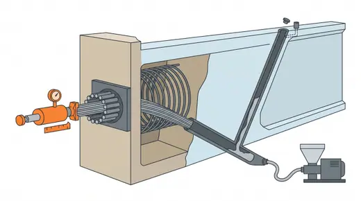
Post-tensioning: tendons, stressing and groutingSteel strands in ducts tensioned after the concrete hardens, anchored at the ends and usually grouted for bond and protection. Internal tendons live inside the concrete; external tendons run inside the box and can be inspected and replaced. Grout quality decides whether the bridge lasts a century or corrodes in twenty years.
Progressive placement of precast segmentsPrecast segments are placed in one direction from one abutment to the other, each span cantilevered from the last pier until it reaches the next, with temporary stays from a mast on the deck or temporary bents carrying the advancing cantilever. All the work comes from the deck already built, which suits curved alignments and sites where nothing but the permanent piers may touch the ground.Full-depth precast deck panels with UHPC or grouted jointsDeck slabs are made of precast panels the full slab thickness, set on the girders and joined either by grouted keyways with longitudinal post-tensioning or by field-cast UHPC joints, with pockets or channels grouted over the shear connectors. Most of the forming, reinforcement fixing and curing leaves the site, so a span can be decked in days or in overnight closures.Continuity over piers for precast girders: stitch pours, diaphragms and link slabsSimply supported precast girders are made continuous over the piers by a cast-in-place diaphragm poured with, or after, the deck over the support; alternatively a link slab ties only the deck slabs together while the girders stay simply supported. Either way the deck joints over the piers disappear, removing the main source of leakage onto bearings and pier caps.

Steel erection

Steel arrives finished from the shop and is assembled in the air. The methods are about carrying pieces to their place, joining them, and keeping the half-built frame stable until the last bolt is tight.
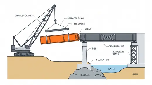
Crane erection of steel girdersPlate girders, box girder sections or truss members are lifted by mobile or crawler cranes from the ground or a trestle onto the piers and temporary supports, then spliced. With ground access it is the simplest steel method and spans to 90 m with temporary towers or by lifting pre-assembled units.in the game
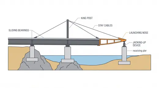
Launching of steel girders and boxesSteel girders assembled behind an abutment are pushed or pulled across the piers on rollers or slide bearings, with a nose ahead and often a temporary king post and stays to control the cantilever. Because steel is light and strong in bending, spans of 60-120 m launch without temporary piers.in the game
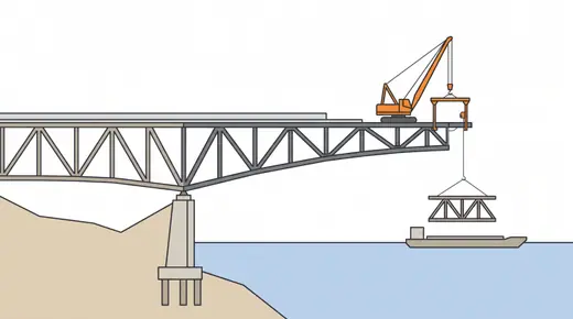
Cantilever erection of steel (derrick and lifting frames)Steel trusses and box girders are built outward from a pier as a cantilever, each new piece lifted by a derrick or creeper crane that rides on the already-erected structure. The great method of cantilever trusses and of long-span steel over navigable water; still used for trusses and for the main spans of cable-supported steel decks.in the game
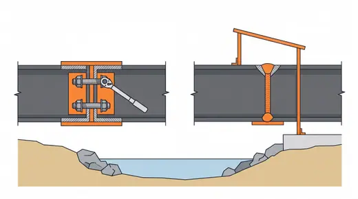
Field splices: bolted and welded connectionsWhere shop lengths meet in the air. Bolted splices with high-strength bolts are the default: quick, inspectable and forgiving of tolerance. Welded splices give a clean box but need weather protection, preheat, skilled welders and full inspection.
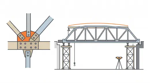
Truss assembly and erectionTrusses are assembled from chords, diagonals and verticals joined at panel points with gusset plates. They can be built on falsework, cantilevered out panel by panel, assembled whole on the bank and floated or slid in, or lifted in sections. The geometry must close: trusses are unforgiving of accumulated error.
Orthotropic steel decksA steel deck plate stiffened by longitudinal closed ribs and transverse floor beams, forming the top of a box girder and carrying traffic directly on a thin surfacing. The lightest deck there is, so long-span cable-stayed and suspension bridges use it; fatigue at the rib-to-deck welds and surfacing debonding are its lifelong issues.
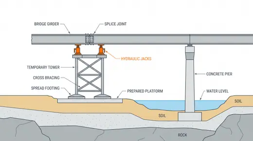
Temporary towers and bents for steel erectionModular steel towers placed under splices so girders can be set in shop lengths and joined before the span acts alone. They must carry the partial structure plus wind and must come out once the span is complete.in the game
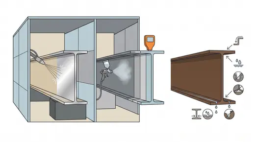
Corrosion protection of steel bridges: coatings and weathering steelSteel bridges live or die by their corrosion protection. Multi-coat paint systems (zinc-rich primer, epoxy, polyurethane) are applied in the shop and touched up on site; metallising adds a sprayed zinc or aluminium layer; weathering steel forms its own patina where the climate lets it dry. The choice sets the maintenance cycle for decades.

Cable-supported and arch bridges

The longest spans are built from the top down: the deck hangs from stays or a main cable, or pushes against an arch, and the structure only works once the last piece is in. These methods are as much about temporary conditions and geometry control as about erection.
Cable-stayed cantilever erectionThe deck of a cable-stayed bridge is built outward from each pylon as a cantilever, each new segment (cast in a traveller or lifted as steel or precast) supported by the stay installed right behind it. The stays are the falsework; the cantilever grows 8-15 m per week from each pylon until closure at midspan and at the side-span piers.in the gameStay cable installation and tensioningModern stays are bundles of 15.7 mm greased and sheathed strands inside an HDPE pipe, installed strand by strand with a small winch and stressed one at a time with a monostrand jack (isotensioning), then adjusted as a bundle. Older and some Japanese bridges use prefabricated parallel wire strands or locked coil ropes installed whole.Extradosed bridge constructionA balanced cantilever box girder with short pylons and stiff external stays that act as prestressing more than as suspension. Built exactly like a cast-in-place cantilever with the stays added in the cycle; spans of 100-275 m with pylons only a tenth of the span high, and stays that hardly fatigue.
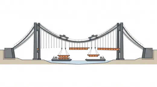
Suspension bridge erection: cables, hangers and deckThe anchorages and towers are built first, a catwalk is hung, the main cables are formed (spun or prefabricated), then the hangers are installed and the deck is lifted in sections from barges below and joined from midspan outward. Every step changes the cable geometry; the sequence is engineered as carefully as the bridge.in the game
Aerial spinning of main cablesA spinning wheel carries loops of 5 mm galvanised wire across the span between the anchorages, thousands of times, building the main cable wire by wire in strands of several hundred wires that are then compacted into a circular cable. The traditional method of American and European suspension bridges; today it competes with PPWS where cables are very large or strand reels are hard to deliver, while PPWS has built the longest spans (Akashi Kaikyo, 1915 Çanakkale).Prefabricated parallel wire strands (PPWS)Main cable strands of 61–127 parallel wires are made in a factory with sockets at both ends, reeled, and hauled across the span one at a time on the catwalk. Faster and less weather-dependent than spinning; developed in the United States (Newport Bridge, 1969) and refined in Japan, where it built Akashi Kaikyo, and used for most Asian suspension bridges since.
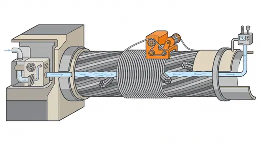
Cable wrapping and dehumidificationMain cables corrode from inside; the modern cure is to wrap them airtight and blow dry air through them at 40 % relative humidity. Applied on new bridges from the start and retrofitted on old ones, it has replaced red lead paste and re-wrapping as the way to keep a cable for a century.
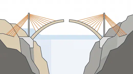
Arch erection by cantilever with temporary staysEach half of an arch is built outward from the springing as a cantilever, held by temporary stay cables running over temporary towers to anchors behind the abutments, until the halves meet at the crown. Concrete arches use form travellers; steel arches lift segments with deck or floating cranes. The method for arches over gorges and rivers where the arch cannot be supported from below.in the game
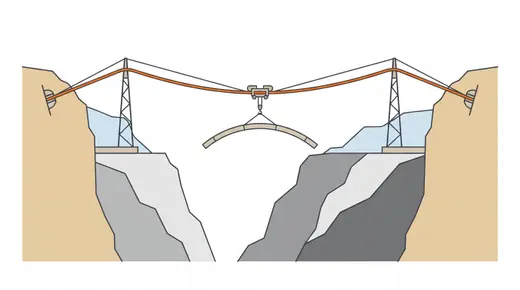
Cable crane (cableway) erectionA carrying cable strung between towers on each side of a gorge with a trolley that lifts arch segments or truss members from the valley floor or the banks and delivers them anywhere along the span. The classic plant of arch bridges in mountains and the standard in Chinese arch construction.in the game
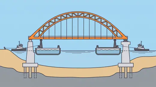
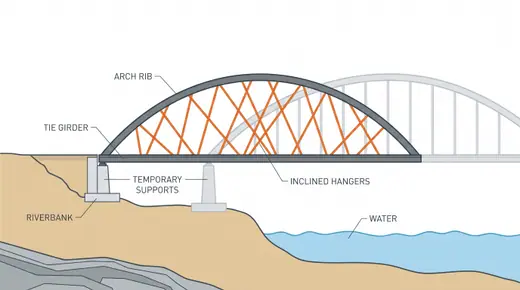
Float-in of complete arches and spansA tied arch or truss is assembled complete on a bank or on barges, floated to the piers and set down by ballasting the barges or by jacking. Site erection is replaced by yard assembly and one tidal window; it suits navigable rivers and harbours where the span must go in quickly.in the game
Network tied arch constructionA network tied arch (inclined hangers crossing twice or more) is light enough to be built whole on falsework or on the bank and moved in, because the arch and tie are slender. The hangers are installed and tensioned in a strict sequence so that none goes slack during the deck pour.
Self-anchored suspension bridge erectionA suspension bridge whose main cables are anchored to the ends of the stiffening girder instead of to the ground, so the deck carries the cable pull as compression. Because the cable needs the deck to anchor it, the deck is built first on temporary supports, the cables are formed and the hangers fitted, and the load is then transferred from the falsework to the cables by jacking the hangers.Concrete-filled steel tube (CFST) arch constructionThe arch ribs are first erected as hollow steel tubes or tube trusses, light enough to place by cable crane or rotation, and are then pumped full of high-strength concrete, so the tubes confine the concrete and the concrete stabilises the tubes. Developed mainly in China since 1990, it now builds arches of 100–575 m, and the same steel skeleton, encased in concrete, forms the core of the longest concrete arches.Stress-ribbon bridge constructionA thin concrete deck hangs as a shallow catenary between abutments; it is built by sliding precast segments along bearing tendons anchored in massive abutments and then prestressing the whole band. It uses very little material but passes very large horizontal forces to the ground, so it suits footbridges and pipeline bridges where the abutments can be anchored in rock or on large piles.

Heavy lift, moving and accelerated construction

Sometimes the fastest way to build a bridge is to build it somewhere else and move it. Floating cranes, strand jacks, self-propelled transporters, slide tracks and rotation bearings put whole spans in place in hours; the engineering is in the temporary condition, the weather window and the closure.
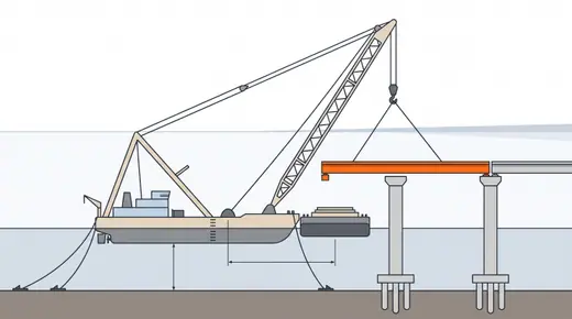
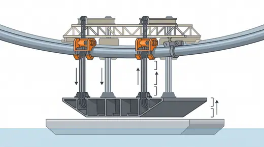
Floating crane erectionA crane barge of 1,000-4,000 t lifts complete spans, steel box sections, arch halves or pylon segments from a delivery barge and sets them on the piers. Where the water is deep enough and calm enough, it replaces months of piece-by-piece erection with days of lifts.in the game
Strand jack liftingHydraulic jacks that climb bundles of strands lift thousands of tonnes slowly and precisely from a gantry on the structure above: deck sections of suspension bridges from barges, arches, and whole spans. Slow but unlimited in capacity and largely independent of crane vessels.in the game
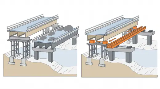
Lateral slide (slide-in bridge construction)The new bridge is built beside the existing one on temporary supports, the old bridge is demolished in a short closure, and the new one is slid sideways onto the permanent supports on PTFE pads with jacks. Traffic loses a weekend instead of a year.in the game
SPMT move (self-propelled modular transporters)Multi-axle hydraulic transporters, computer-controlled and combined into one platform, drive under a complete superstructure built nearby, lift it, carry it to the crossing and lower it onto the piers. A 2,000 t bridge moves in a night; the transporters need only a level path.in the gameRotation (swing) constructionThe bridge or its arch halves are built parallel to a railway or river on a pivot bearing, then rotated horizontally into position in a few hours during a possession. Vertical rotation raises arch halves built lying near the ground. A Chinese speciality now used worldwide for rail crossings where the track can only be closed briefly.in the gameTop-down construction over wetlandsThe viaduct builds itself: piles are driven from a crane on the completed deck, precast girders are delivered along the deck and set by a launching girder or a crane at the end, and the next span becomes the road for the next pier. No trestle, no ground access, and the wetland underneath is untouched.in the game
Prefabricated bridge elements and systems (PBES)The systems view of accelerated bridge construction: footings, columns, caps, girders with deck attached, full-depth deck panels and even complete spans as prefabricated modules with engineered connections, assembled on site in days. The game's precast pier and full-span options are parts of this.
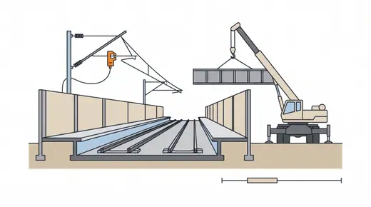
Working over live railways: possessions and blockadesAnything over a live railway is built inside possessions: short overnight closures of a few hours, or planned blockades of a weekend. The method is planning: everything is prepared, every lift is rehearsed, and the possession is used only for what cannot be done with trains running.
Bridge jacking and liftingLifting an existing or new deck on hydraulic jacks: to replace bearings, to raise a bridge for clearance, to correct settlement, or to lift a launched deck onto its bearings. Millimetres matter, and every jack must move together.Floating (pontoon) bridge construction and towingA deck carried on watertight pontoons that float on the water, held in place by anchor cables or by fixed abutments, used where the water is too deep or the bed too soft for piers. The pontoons are cast in a dry dock or casting basin, floated out, towed to site, joined afloat and moored; the engineering is in buoyancy, moorings, watertightness and the transition spans to the shore.Box jacking and pipe-roof jacking under railways and roadsA reinforced concrete box (underpass, culvert or short tunnel) is cast in a jacking pit beside a railway or road embankment and pushed horizontally through the ground by hydraulic jacks while soil is excavated at a shield in front, so the traffic above keeps running. Where cover is small or the ground loose, a canopy of jacked steel pipes (pipe roof), anti-drag cables, ground freezing or grouting supports the ground above the box.Modular temporary and emergency bridges (Bailey, Acrow, Mabey)Prefabricated steel truss panels pinned end to end into girders, joined by transoms and deck units, form a bridge that a small crew can assemble without heavy plant and launch across a gap in days. Derived from the 1941 Bailey bridge, modern systems carry full highway loading and serve as emergency replacements, construction detours and permanent bridges in remote areas.

Finishing, articulation and maintenance

A bridge is finished when the traffic can use it and it can be kept: bearings and joints let it move, waterproofing and surfacing keep water out, barriers keep vehicles on. Then it must be inspected, strengthened, repaired and one day taken down.
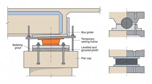
Bearing installation and settingBearings carry the deck load to the pier while letting it rotate and move. Elastomeric pads for short spans, pot and spherical bearings for heavy loads and large movements, lead-rubber and friction pendulum bearings for seismic isolation. Setting them level, aligned and pre-set for temperature decides whether they work for fifty years or are replaced in ten.
Expansion jointsThe gap where the deck ends and the abutment begins, bridged by a device that carries wheels and moves with the deck: buried and asphaltic plug joints up to about 40–50 mm, strip seals to about 100 mm, finger plates and modular joints from a few hundred millimetres to about 2,000 mm on long bridges. Joints leak, wear and are the first thing replaced; the best joint is none.
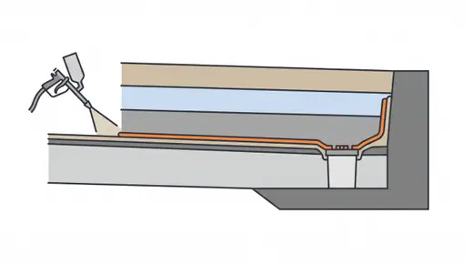
Deck waterproofing and drainageConcrete decks under asphalt are protected by a membrane (sprayed polyurethane or methacrylate, sheet bitumen or liquid systems) that keeps chloride-laden water off the reinforcement. With gullies, drains and drip details it is the difference between a deck that lasts and one that delaminates.
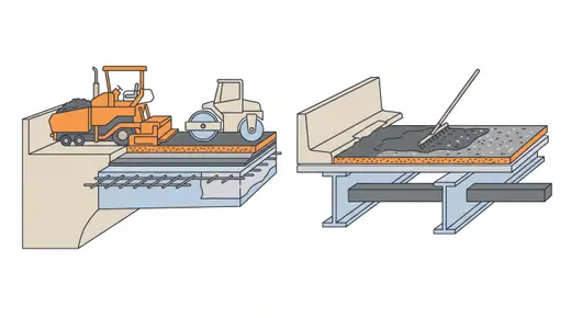
Surfacing: asphalt, SMA, concrete and thin overlaysThe wearing surface: dense asphalt or stone mastic asphalt over a membrane on concrete decks, mastic (Gussasphalt) or epoxy asphalt on orthotropic steel, thin polymer overlays where weight or skid resistance rule, or the bare concrete deck with a texture. The game's pavement question is this choice.
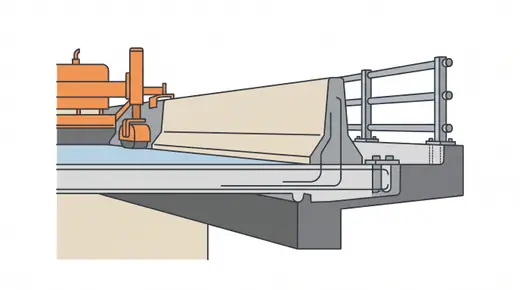
Parapets, barriers and edge detailsThe concrete or steel barrier along the deck edge that keeps vehicles on the bridge, tested to a containment level; plus the kerbs, drip grooves, cable troughs and noise screens that finish the edge. Slipformed concrete barriers finish a kilometre a day; steel parapets bolt to cast-in sockets.
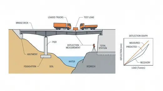
Load testing, inspection and handoverBefore traffic, the bridge is loaded with trucks at known positions and its deflections compared with the analysis; a dynamic test measures frequencies and damping. Together with the inspection of every component and the as-built records, it is the last hold point and the first entry in the maintenance file.
Bearing replacementBearings wear out or corrode long before the bridge does. The deck is jacked a few millimetres at the pier, the old bearing removed, the plinth repaired and the new bearing set; often under traffic with lane closures.Strengthening: external post-tensioning and FRPWhen a bridge must carry more than it was built for, or has lost capacity, it is strengthened: external tendons inside the box or under the deck add prestress; bonded carbon fibre plates and sheets add tension capacity to slabs, girders and piers; steel plates and jackets do the same in heavier form.
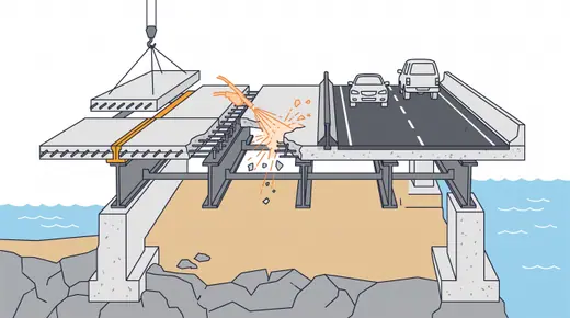
Deck replacement and wideningThe deck slab wears out first: chlorides, freeze-thaw, traffic. It is replaced in stages under traffic, or overnight with full-depth precast panels, while the girders are kept; widening adds girders and a new slab alongside, tied to the old with dowels and a longitudinal joint.
Bridge demolition and deconstructionTaking a bridge down is construction in reverse with less information: the old drawings may be wrong and the post-tensioning may be corroded. Decks are cut into pieces and lifted, launched back, lowered by strand jacks, or dropped in a controlled sequence; explosives are used only where a wide exclusion zone can be cleared, which includes some urban sites.
FRP strengthening: bonded laminates, sheets and near-surface mounted barsCarbon (sometimes glass or aramid) fibre laminates, sheets or bars are bonded with epoxy to concrete, steel, timber or masonry to add tension, shear or confinement capacity without adding weight. It is quick and needs little access, but it is only as good as the substrate and the bond, and it does not reduce the stresses already in the member.Seismic retrofit: jacketing, restrainers, seat extensions and isolationBridges designed before modern seismic codes fail in a few predictable ways: spans fall off short seats, columns fail in shear or at lap splices, and footings, caps and joints are under-reinforced. Retrofit adds what is missing in order of risk: restrainers and seat extensions first, then column jackets for ductility and shear, then foundation, joint or isolation work where the analysis requires it.Stay cable and hanger replacementStays, hangers and suspenders are replaceable parts: corrosion of grouted strands, broken wires at sockets, fatigue at anchorages or failed sheathing eventually force their renewal. One cable at a time is released and replaced while the others carry the load, usually under traffic restrictions, with the deck geometry and pylon forces controlled at every stage.Bonded deck overlays: latex-modified, silica fume, UHPC and polymerA thin bonded layer replaces the worn, cracked or chloride-loaded top of a concrete deck and becomes its new wearing and protective surface. Latex-modified and silica fume concrete overlays are 30–50 mm thick, UHPC overlays 25–50 mm with near-zero permeability, and polymer overlays 6–25 mm where weight and closure time must be minimal.Cathodic protection of reinforced concreteA small direct current makes the reinforcement the cathode of an electrochemical cell, so it stops corroding even in chloride-contaminated concrete. Impressed current systems use a power supply and inert anodes (titanium mesh or ribbon, discrete anodes, conductive coatings) and last decades; galvanic systems use zinc anodes that corrode instead of the steel, without power, for local or shorter-term protection.Link slabs and joint eliminationA chain of simply supported spans is made jointless over the piers by casting a short, debonded slab across each gap that bends with the girder end rotations, while the end joints are moved off the bridge with semi-integral ends or sleeper slabs. It removes the leaking joints that destroy bearings, girder ends and pier caps.Concrete repair: patching, sprayed concrete and crack injectionDeteriorated concrete around corroding or exposed reinforcement is removed, the steel is cleaned or supplemented, and the section is rebuilt with hand-applied mortar, formed and poured concrete or sprayed concrete; cracks are sealed or structurally bonded by low-pressure injection. Done properly it restores section and cover, but done alone in chloride-contaminated concrete it often fails within a decade at the edges of the patches.Repainting steel bridges with containmentThe corrosion protection of an existing steel bridge is restored by spot repair, by overcoating sound old paint, or by full removal to bare steel and a new system. Old lead and chromate paints make removal a hazardous-waste operation, so the work is enclosed, the blast debris is collected, and workers and the surroundings are monitored.