Also called: rock socket design, bell-out, base grouting, shaft grouting
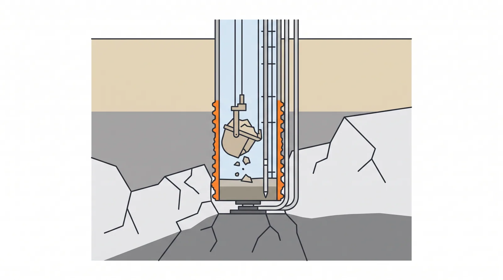
How it is done
- Define sound rock and the socket criteria in the contract (rock type, RQD, strength, minimum socket length) from cored boreholes at or near each pier; probe ahead where the rock level varies.
- Seat the casing or standpipe into rock to cut off soil inflow, then drill the socket with core barrels, rock augers, roller bits or a hydromill; in karst or mixed ground, drill a probe hole at least about 3 m (1–2 diameters) below the toe to check for cavities.
- Roughen the socket wall with grooving tools or side cutters where the design relies on high shaft resistance, and remove smear from clayey rock with cleaning passes.
- Clean the base with a cleaning bucket, airlift or reverse circulation until the returns are clear; measure debris with a sediment probe, weighted tape or downhole camera. Hold point.
- Log the socket where possible (camera, sonic caliper), compare the actual rock level with design, and adjust the socket length by the agreed rules.
- Concrete promptly after cleaning, before slaking rocks such as mudstone soften; where end bearing is needed but the base cannot be proved clean, add base grouting (see post-grouting).
- Verify with bi-directional (O-cell) tests, which separate socket shaft and base resistance.
Key numbers
- Socket lengthtypically 1–3 diameters into competent rock; longer in weak rock
- Unit shaft resistanceoften estimated as 0.2–0.3 × √qu (MPa) for normal sockets (Horvath and Kenney)
- Ultimate end bearingabout 2.5 qu for sound rock, reduced for jointed rock mass
- Base debris where end bearing is used≤ 13 mm over half the base, ≤ 38 mm maximum (FHWA)
- Measured side resistance at Benicia–Martinezabout 280–370 kPa in most layers
Where it fits
- All rock-socketed shafts; base grouting in sands and weak rock where end bearing is needed.
Where it does not
- Relying on end bearing on a base that has not been measured clean.
Choosing it
- Choose a longer socket in weaker rock over relying on base resistance in uncertain rock: shaft resistance is reliable, base resistance depends on cleanliness.
- Choose base grouting where end bearing is wanted but the base of a deep marine hole cannot be proved clean.
- Prefer a spread footing or caisson founded directly on rock when rock is shallow and dry access is possible; a socket then adds cost for little gain.
- Prefer barrettes cut by a hydromill where strong rock and boulders make round sockets slow.
Plant, pace and money
Risks and controls
What goes wrong
- Smear of soil on the socket wall, debris at the base, grout leaking around the cage.
Quality assurance
Sediment probe readings before concreting, grout pressure and volume records, O-cell test to confirm socket resistance.
Origins
Socket design rules took their modern form between the late 1970s and late 1980s from instrumented tests in Canada and Australia (Horvath and Kenney 1979; Williams and Pells 1981; Rowe and Armitage 1987); bi-directional testing from the 1990s made it practical to measure socket resistance on production-size shafts.
Examples
Base grouting is standard practice in Southeast Asian sands and on many Chinese sea bridge pylons.
Case studies
Related methods
Further reading
FHWA GEC 10 · Horvath and Kenney, shaft resistance of rock-socketed piles · Rowe and Armitage (1987), a design method for drilled piers in soft rock · Williams and Pells (1981), side resistance of rock sockets in sandstone, mudstone and shale · NCHRP Synthesis 360, Rock-Socketed Shafts for Highway Structure Foundations