Also called: bored pile, drilled shaft, cast-in-drilled-hole pile, CIDH
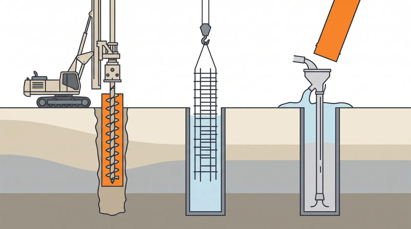
How it is done
- Set out the pile and build a working platform that can carry the rig and service crane; check for services and obstructions. At sea, install the piled platform or position the jack-up first.
- Install a temporary or permanent casing through the soft, loose or scourable upper soils (vibrated, oscillated or drilled in), plumb and sealed into a competent layer.
- Drill below the casing with augers and drilling buckets, under bentonite or polymer slurry where the ground is water-bearing or unstable, or dry in stable clay; keep the fluid level above the groundwater head at all times.
- Drill the rock socket with core barrels or rock augers to the level confirmed against the boring logs and the cuttings, logging every metre.
- Clean the base with a cleaning bucket or airlift, then check depth, verticality and base debris (weighted tape, sediment probe or camera) and test the slurry. This is the hold point before the cage goes in.
- Lower the cage with spacers and CSL tubes, hung so it cannot sink or float; place the concrete by tremie in one continuous pour with the pipe embedded, withdrawing any temporary casing as the concrete rises.
- Overpour, break down to sound concrete at cut-off, run CSL on every pile after about 3–7 days, and load test a sample pile in each ground type (static, bi-directional or rapid).
Key numbers
- Diameter0.6–3.0 m (bridge piers mostly 1.2–2.5 m; sea pylons 2.5–3.0 m)
- Depth15–60 m typical; over 100 m for large marine piles in deep soil (Sutong 114–117 m)
- Working load3–30 MN per pile; 30–60 MN for 2.5–3 m shafts socketed in rock
- Plan tolerance±75 mm typical (EN 1536 allows ±100–150 mm depending on diameter)
- Verticality1:50 common; 1:100–1:200 or better specified for deep marine piles
- Base debris where end bearing counts≤ 13 mm over at least half the base and ≤ 38 mm anywhere (FHWA)
- Concrete takeusually 5–15 % above theoretical in soil; an under-run points to necking or collapse
Where it fits
- Loads of 5-50 MN per pile, rock sockets, boulders and cobbles, urban noise limits, river piers where driven piles would refuse; almost any site with a rig large enough.
Where it does not
- Very loose sands under high water pressure without adequate slurry head (hole collapse).
- Artesian layers (the game's blowout event) without casing through them.
- Sites where a driven pile would simply be cheaper.
Choosing it
- Choose it over driven piles when loads per pile exceed about 5–10 MN, when rock must be socketed, or when noise and vibration limits rule out hammers.
- Prefer driven steel or concrete piles in soft to medium soils without obstructions where many moderate-load piles are needed; they are proven by set and are faster.
- Prefer CFA piles for land viaducts on soil with loads under about 3–5 MN; compare a caisson or barrettes when scour, ship impact or moments would demand very large shaft groups.
- Keep permanent steel casing through soft or scourable layers when lateral stiffness and buckling govern: at Charleston a permanently cased shaft deflected less than half as much as a temporarily cased one.
Plant, pace and money
Risks and controls
What goes wrong
- Base debris and soft toe, necking where the casing is withdrawn too fast, slurry contamination of the concrete, cage lifting during pouring, hole collapse. Every one of these is invisible until tested.
Quality assurance
Base cleanliness measured by sounding or sediment probe, slurry density and sand content before concreting, concrete volume against theoretical per pile, CSL on every pile, one static or O-cell test per pile type.
Origins
Machine-drilled shafts grew out of the hand-dug Chicago and Gow caissons of the 1890s and the truck-mounted augers adapted from oil-well drilling in Texas in the 1930s–40s. Bentonite support, introduced by Christian Veder for diaphragm walls in Italy in the 1950s, made deep uncased bored piles routine by the 1960s.
Examples
The default foundation for pylons and river piers on rock or deep soil: Sutong (131 piles of 2.5–2.8 m under each pylon), the Arthur Ravenel Jr. Bridge in Charleston and the Mumbai Trans Harbour Link. The game's reference picks it under pylons and river piers on rock.
Case studies
Related methods
Further reading
FHWA GEC 10 Drilled Shafts · EN 1536 (bored piles) · O'Neill and Reese · O'Neill and Reese (1999), Drilled Shafts: Construction Procedures and Design Methods (FHWA-IF-99-025) · ADSC/DFI Drilled Shaft Inspector's Manual · Fleming, Weltman, Randolph and Elson, Piling Engineering · ICE Specification for Piling and Embedded Retaining Walls (SPERW)