Also called: basal reinforced piled embankment, geosynthetic-reinforced pile-supported embankment, GRPS
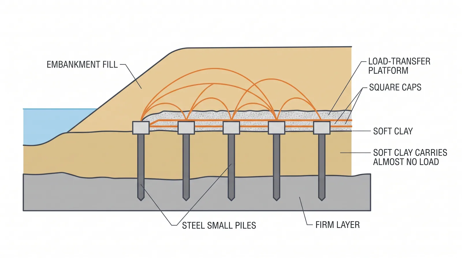
How it is done
- Design the pile grid and caps for load transfer by arching (BS 8006-1, EBGEO or CUR 226), the geosynthetic for the vertical load between caps and for lateral sliding at the edges, and check the differential settlement at the surface.
- Install piles on a 1.5–3.0 m grid: driven precast or timber, CFA, vibro concrete columns, or DCM and stone columns for lighter cases; cut them to level.
- Cast pile caps of about 0.6–1.5 m square, or a continuous slab in transition zones.
- Place a thin granular layer and the first geogrid just above the caps, laid flat with design overlaps and the strong direction across the embankment.
- Build the 0.5–1.0 m load-transfer platform of compacted granular fill with one to three geogrid layers.
- Build the embankment; arching needs a fill height of at least about 0.7 times the clear spacing between caps, and below that the surface shows differential settlement.
- Monitor settlement of the caps and of the ground between them, and the strain in the geogrid.
Key numbers
- Pile grid 1.5–3.0 m; caps 0.6–1.5 m; caps cover typically 10–30 % of the area.
- Minimum height for full archingH ≥ 0.7 (s − a), where s is pile spacing and a is cap width (BS 8006-1).
- Load-transfer platform 0.5–1.0 m with one to three geogrid layers of about 200–1,000 kN/m short-term strength.
- Costabout two to four times a PVD scheme for the same footprint.
Where it fits
- Approaches on very soft or organic soil, where the programme is short, or where the approach must not settle against a fixed abutment.
Where it does not
- Thin soft layers where PVDs are far cheaper.
Choosing it
- Choose a piled embankment over PVD and surcharge when there is no consolidation time, the soil is organic or peat, or the approach must not settle against a piled abutment.
- Prefer PVDs where there is time and the soft layer is thin to moderate: piled embankments cost several times more.
- Prefer rigid piles (precast, CFA, cement-fly ash-gravel) to stone columns or DCM for high fills and creep-prone soils; columns are cheaper but less stiff.
- Prefer a piled concrete slab to a geosynthetic platform in the transition zone next to the abutment, where differential settlement must be smallest.
Plant, pace and money
Risks and controls
What goes wrong
- Punching of caps through the platform if the geogrid is under-designed; lateral spreading at the embankment toe.
Quality assurance
Pile records, geogrid overlap and tension checks, settlement plates on caps and between them.
Origins
Piled embankments with timber or concrete piles and caps were used in Scandinavia and the Netherlands from the 1960s and 1970s; geosynthetic load-transfer platforms followed in the 1980s, with design methods from Hewlett and Randolph (1988), BS 8006 (1995), EBGEO (2010) and CUR 226 (2010).
Examples
Dutch and Scandinavian railways, Korean high-speed rail approaches, Bangkok expressway ramps.
Case studies
Related methods
Further reading
BS 8006-1 · CUR 226 (Dutch design guideline) · EBGEO, Recommendations for Design and Analysis of Earth Structures using Geosynthetic Reinforcements (German Geotechnical Society) · Hewlett and Randolph (1988) Analysis of piled embankments