Also called: wick drains, PVD and preload, band drains
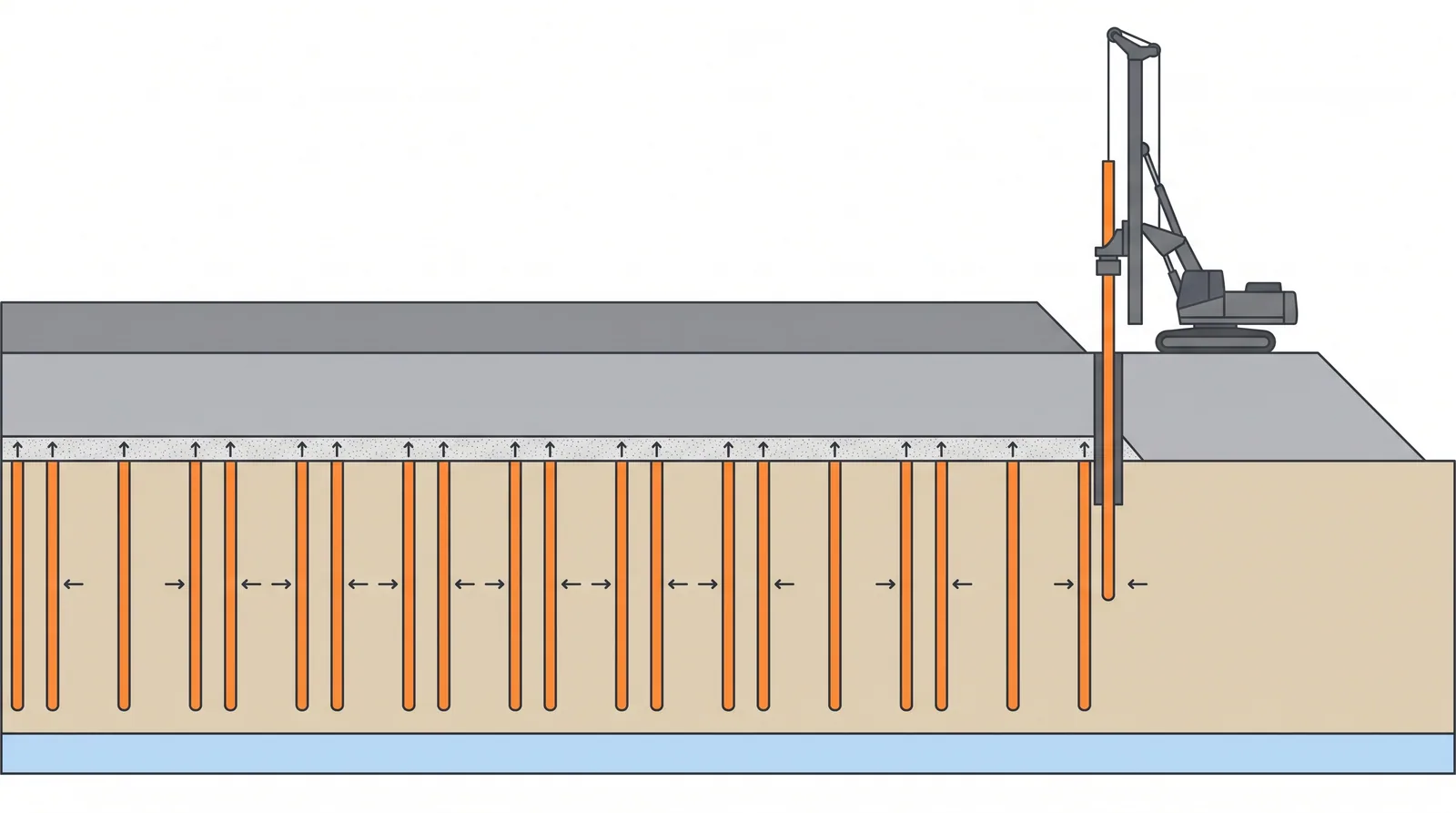
How it is done
- Characterise the soft layer: CPTu with dissipation tests for the horizontal consolidation coefficient, oedometer or CRS tests on good samples for compressibility and stress history, and the drainage boundaries above and below.
- Design drain spacing for the target degree of consolidation in the time available (Barron and Hansbo theory with smear and well resistance), and stage the embankment, with berms or basal reinforcement where stability requires.
- Place a sand drainage blanket of about 0.5–1.0 m with outlets, then install settlement plates and piezometers before the drains go in.
- Install PVDs with a closed mandrel and anchor plate on a square or triangular grid to the base of the soft layer, recording depth and position for every drain.
- Build the embankment in stages, holding each until pore pressures have dissipated enough, then add a surcharge of 1–3 m above final level.
- Monitor settlement and pore pressure and fit Asaoka or hyperbolic curves to estimate final settlement and the degree of consolidation reached.
- Remove the surcharge only when the target consolidation (typically 90 % or more) and the residual settlement limit are met; then build the pavement and approach slab and keep monitoring into the defects period.
Key numbers
- Band drains about 100 × 3–5 mm, equivalent diameter about 50–65 mm.
- Spacing 1.0–2.5 m; installed depth typically 10–30 m, with long-mast rigs reaching about 40–50 m.
- Surcharge1–3 m of fill above final level.
- Time to 90 % consolidationcommonly 3–12 months at 1.0–1.5 m spacing in soft marine clay.
- Smear zoneabout 2–3 times the mandrel equivalent diameter, with permeability reduced several times.
- Output3,000–8,000 m of drain per rig per day.
Where it fits
- Approach embankments and MSE abutments on soft clay 5-30 m thick.
- Projects with a year of programme to spend before the pavement goes down.
Where it does not
- Peat and very organic soils, which creep after primary consolidation.
- Programmes that cannot wait: use piled embankments instead.
Choosing it
- Choose PVD and surcharge over piled embankments when there are 6–12 months to spend and fill is available: it is typically several times cheaper.
- Prefer vacuum consolidation, alone or with fill, when fill is scarce or staged loading would be unstable; the vacuum adds no outward shear stress.
- Prefer piled embankments, DCM or lightweight fill beside abutments where residual and creep settlement must be close to zero, and in peat.
- Combine PVDs with stone columns or DCM when both drainage and early stiffness are needed.
Plant, pace and money
Risks and controls
What goes wrong
- Embankment instability during staged loading.
- Smear around the mandrel slowing drainage.
- Removing the surcharge too early: residual settlement damages the approach slab and the expansion joint.
Quality assurance
Settlement plates every 50 m, piezometers in each soft layer, Asaoka plots to confirm the degree of consolidation before release.
Origins
Sand drains were patented by Daniel Moran in the 1920s and first used by the California Division of Highways in 1934; Kjellman introduced cardboard wick drains in Sweden in 1937, Barron (1948) and Hansbo (1979–81) provided the theory, and plastic band drains replaced sand drains from the 1970s.
Examples
Incheon and Busan reclamations, Bangkok and Ho Chi Minh City approaches, the Gulf sabkha coasts.
Case studies
Related methods
Further reading
Holtz et al., Prefabricated Vertical Drains (FHWA) · EN 15237 · Hansbo (1981) Consolidation of fine-grained soils by prefabricated drains · Barron (1948) Consolidation of fine-grained soils by drain wells · Indraratna, Chu and Rujikiatkamjorn (eds), Ground Improvement Case Histories: Embankments with Special Reference to Consolidation and Other Physical Methods