Also called: cyclic resistance, seismic ground hazard
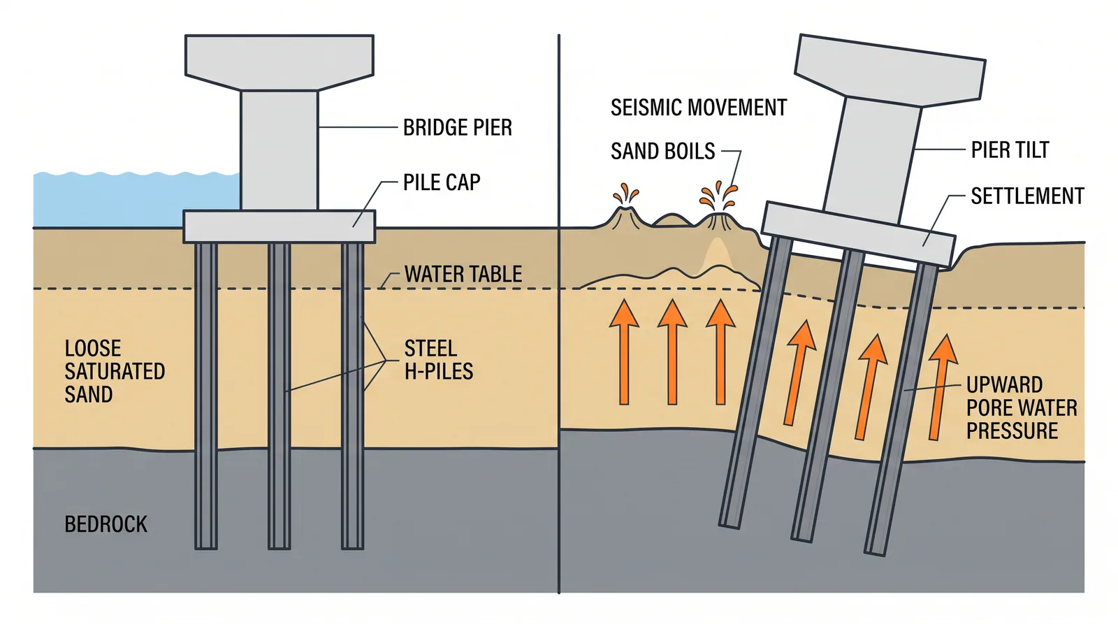
How it is done
- Screen for susceptibility: young alluvium, hydraulic fill and reclaimed land, groundwater depth, and grading and plasticity of the fines.
- Set the design motion (peak acceleration and magnitude for the bridge's performance level); run a site response analysis where soft deep soils change the motion.
- Characterise each layer with CPTu soundings, SPTs with fines content and Atterberg limits on samples, and shear-wave velocity where needed.
- Compute the cyclic stress ratio with depth and the cyclic resistance from corrected cone resistance or N-values, with one consistent procedure including magnitude and overburden corrections.
- Assess the consequences: post-liquefaction settlement, residual strength, lateral spreading toward channels and slopes, downdrag on piles, and stability of abutments and approach fills.
- Design piles for kinematic loads, loss of lateral support and lateral spread forces through liquefied layers, or treat the ground (vibro-compaction, stone columns, DCM, drains).
- Verify any treatment with post-treatment CPTs against the target cyclic resistance.
Key numbers
- Simplified procedureCSR = 0.65 (amax/g)(σv0/σ'v0) rd; factor of safety = CRR/CSR.
- Fine-grained soils with PI of 7 or more generally behave as clay rather than sand (Boulanger and Idriss, 2006).
- Assessment depth commonly 20 m below ground; deeper layers need overburden corrections and are rarely critical.
- Post-liquefaction volumetric strainabout 1–5 % of layer thickness in loose clean sand.
- Common target after mitigationfactor of safety of 1.1–1.3 in the treated zone.
Where it fits
- Moderate and high seismic zones with young alluvium, reclaimed fill, estuaries and river banks.
Where it does not
- Ignoring thin liquefiable seams under footings; they matter more than deep ones.
Choosing it
- Use CPTu as the primary tool and SPT with fines content as a check in critical layers: the CPT is continuous and finds thin seams.
- Treat the ground when abutments and approach fills would spread; design the piles through the layer when only the piers are affected and the layer is thin.
- Prefer a site-specific response analysis to code spectra on soft, deep sites, where amplification can change the cyclic stress either way.
- Prefer cyclic laboratory tests on high-quality samples for silts and intermediate soils, where CPT and SPT correlations are least reliable.
Plant, pace and money
Risks and controls
What goes wrong
- Fines corrections are the largest uncertainty; use both SPT and CPT where the layer is critical.
Quality assurance
Independent check of the design motion and of the corrections applied.
Origins
Seed and Idriss published the simplified procedure in 1971 after the 1964 Niigata and Alaska earthquakes; CPT-based methods (Robertson and Wride, 1998), the NCEER consensus (Youd et al., 2001) and Idriss and Boulanger (2008, 2014) refined it into current practice.
Examples
Niigata 1964 (Showa Bridge) is the classic liquefaction failure of a bridge. At Kobe in 1995 liquefaction mainly damaged structures on reclaimed land, while the best-known viaduct collapses were structural column failures. The game raises seismic zones on estuary and reclaimed sites.
Case studies
Related methods
Further reading
Idriss and Boulanger, Soil Liquefaction During Earthquakes · AASHTO LRFD Seismic Guide Specifications · Seed and Idriss (1971) Simplified procedure for evaluating soil liquefaction potential · Youd et al. (2001) NCEER/NSF workshop summary on liquefaction resistance · Ashford, Boulanger and Brandenberg, Recommended Design Practice for Pile Foundations in Laterally Spreading Ground (PEER Report 2011/04)