Also called: high-strain dynamic test, PDA, CAPWAP
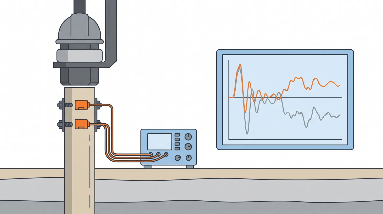
How it is done
- Plan which piles to test and when: end of initial drive and restrike after set-up for driven piles; for bored piles, a drop weight of 1–2 % of the resistance to be mobilised.
- Prepare the pile: bolt or drill mounting points at least 1.5–2 diameters below the head of driven piles; for bored piles build a level, reinforced or steel-cased head extension of similar length.
- Attach two strain transducers and two accelerometers on opposite faces, and check that force and velocity are proportional at impact before taking data.
- During driving, monitor every blow for stresses, transferred energy and integrity; for test blows on bored piles, raise the drop height in steps until the permanent set is about 2–3 mm per blow.
- Run signal matching (CAPWAP or equivalent) on a representative blow to obtain mobilised resistance, its split between shaft and toe, and the quake and damping values.
- Compare the results with the static design and with static load tests for each pile type; report capacity, driving stresses, energy and the integrity factor for each pile.
Key numbers
- Sensor positionat least 1.5–2 pile diameters below the head.
- Drop weight for bored and cast-in-place piles: 1–2 % of the resistance to be mobilised; target set about 2–3 mm per blow.
- Integrity factor β1.0 uniform, 0.8–1.0 slight damage, 0.6–0.8 damage, below 0.6 broken (Rausche and Goble).
- Driving stress limit for steel piles0.9 fy (AASHTO).
- AASHTO LRFD resistance factor with signal matching at restrike on at least 2 % of piles: 0.65.
- Output5–15 piles per day.
Where it fits
- Driven piles at end of drive and restrike (setup, relaxation), bored piles in numbers, quality control across a site.
Where it does not
- Using it as the only capacity proof for large or unusual piles.
Choosing it
- Choose dynamic testing over static testing to cover many piles quickly and to control driving (stresses, hammer performance, set-up).
- Prefer static or bi-directional tests for the governing capacity of large bored piles, or wherever the hammer cannot mobilise the base.
- Prefer a rapid load test to drop-weight testing on large bored piles where dynamic signals are hard to interpret, accepting its higher cost.
- Restrike driven piles in clay after set-up rather than accepting end-of-drive capacity; in dense sand, restrike to check for relaxation.
Plant, pace and money
Risks and controls
What goes wrong
- Insufficient hammer energy to mobilise the base; results then underestimate capacity.
- Restrike timing: too early misses setup.
Quality assurance
Correlate with at least one static test per pile type; report hammer energy and mobilised set for each blow.
Origins
Smith published the wave-equation analysis of pile driving in 1960; Goble, Rausche and Likins developed the Case method at Case Institute of Technology from 1964, the Pile Driving Analyzer and CAPWAP were commercialised in the 1970s, and ASTM D4945 followed in 1989.
Examples
Routine on PHC and steel pipe pile projects in Korea, Japan and the Gulf.
Case studies
Related methods
Further reading
ASTM D4945 · ISO 22477-4 (dynamic load testing of piles) · ISO 22477-10 (rapid load testing of piles) · Smith (1960) Pile-driving analysis by the wave equation · Rausche, Goble and Likins (1985) Dynamic determination of pile capacity · FHWA GEC 12 Design and Construction of Driven Pile Foundations