How bridges get built · Ground improvement · Dynamic compaction
Also called: heavy tamping, dynamic consolidation
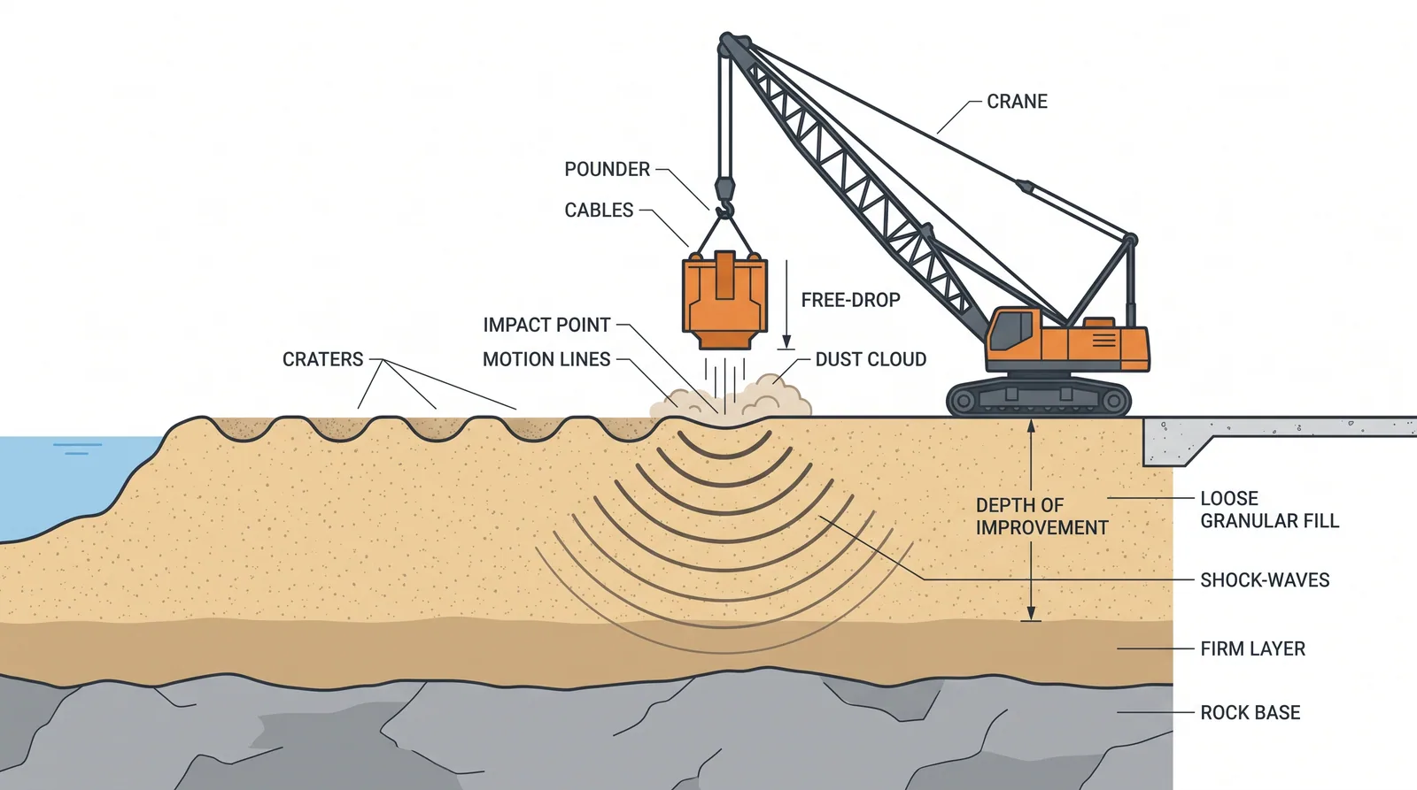
How it is done
- Confirm the material (granular fill, rubble, collapsible soil) and the groundwater depth, test the ground before treatment, and run a trial area to fix energy, grid, drops per point and number of passes.
- Place a granular working platform where the surface is weak, and keep the water table at least about 2 m below the working level, dewatering if needed.
- Make the first, high-energy pass on a wide grid of about 5–10 m with 5–15 drops per point, measuring crater depth after each drop and stopping when further drops add little.
- Backfill the craters with granular material and allow excess pore pressure to dissipate, which takes days to weeks, before the next pass.
- Make the second and any later passes on intermediate grid points to treat the zone between the first prints.
- Finish with an ironing pass of low drops on overlapping prints to compact the top 1–2 m.
- Verify with CPT, SPT or pressuremeter tests and plate load tests against the targets; monitor vibration at the boundary and the induced settlement.
Key numbers
- Depth of improvement D ≈ n √(W·H), with W in tonnes and H in metres; n is about 0.3–0.8, often 0.5.
- Tamper typically 10–25 t dropped 10–25 m; heavier tampers and higher drops need special rigs.
- Effective depth typically 6–12 m.
- Grid 5–10 m on the first pass; 5–15 drops per point; two or three passes plus ironing.
- Induced settlementtypically about 3–10 % of the treated thickness.
- Keep 30–50 m from vibration-sensitive structures and services unless monitoring shows otherwise.
Where it fits
- Loose sand and gravel fill, rubble, reclaimed land, old industrial sites under approaches.
- Depths to about 10 m.
Where it does not
- Saturated clays and silts (no densification, only pore pressure).
- Within 30-50 m of structures or services sensitive to vibration.
Choosing it
- Choose dynamic compaction over vibro-compaction for coarse or unsaturated fills, rubble and collapsible soils to about 10 m on open sites: it is cheaper and treats debris a vibroflot cannot penetrate.
- Prefer vibro-compaction for deeper, saturated clean sands, and wherever vibration and flying debris near neighbours are unacceptable.
- Prefer dynamic replacement or stone columns in silts and soft clays, where tamping alone only raises pore pressure.
- Prefer rapid impact compaction for shallow treatment of a few metres on confined sites.
Plant, pace and money
PlantLarge crawler crane (100-200 t) with a free-fall drum and a tamper.
Productivity2,000-5,000 m2 per crane per week.
CostUSD 8-20 per m2.
Risks and controls
What goes wrong
- Vibration damage, flying debris, crane fatigue.
Quality assurance
Pre- and post-CPT, plate load tests, vibration monitoring at the site boundary.
Origins
Louis Ménard developed dynamic compaction in France in 1968 and first applied it in 1969 at a residential resort in Mandelieu-la-Napoule; Ménard extended it to clayey soils as dynamic replacement in 1975, and FHWA's guidance (GEC 1) codified US practice.
Examples
Airport and port fills; occasionally bridge approaches on rubble fill.
Case studies
Residential resort, Mandelieu-la-NapouleFrance · 1969First application of dynamic compaction, by Ménard.
Nice Côte d'Azur AirportFrance · 1978Dynamic compaction treated reclaimed land for the airport extension; Ménard reports it as its deepest dynamic compaction application, about 27 m.
Related methods
Further reading
FHWA Dynamic Compaction guideline (GEC 1) · Ménard and Broise (1975) Theoretical and practical aspects of dynamic consolidation · Mayne, Jones and Dumas (1984) Ground response to dynamic compaction