How bridges get built · Piers, pylons and abutments · Pylon construction: concrete, anchorage zones and geometry
Also called: tower construction, cable-stayed pylon, pylon anchor box
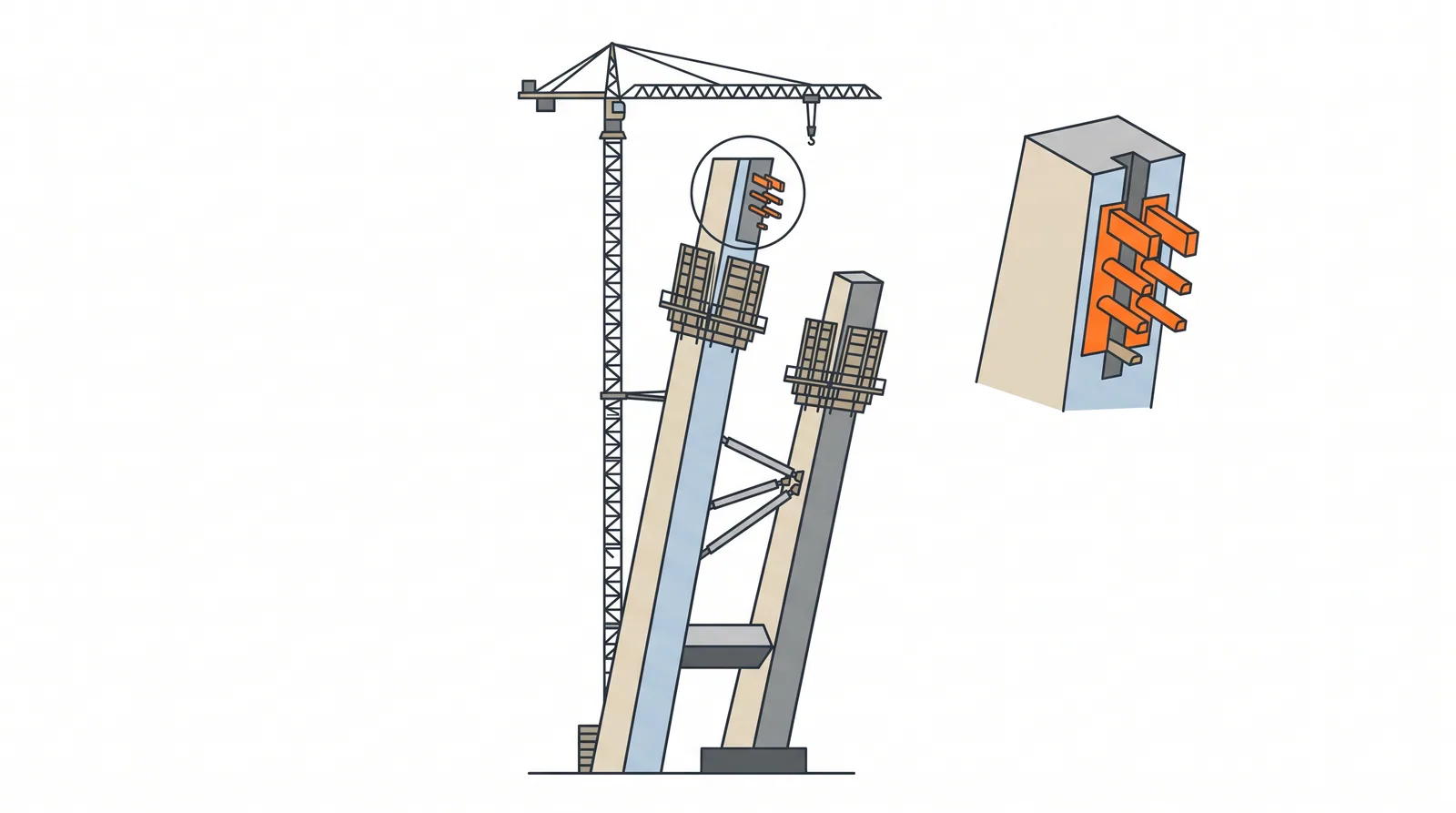
How it is done
- Set up the survey control: reference stations off the structure, total stations and GNSS on the pylon, and temperature sensors, so every lift can be corrected for sun, wind and shortening.
- Climb the legs in 4–5 m lifts with climbing formwork; on inclined legs install temporary horizontal struts, often jacked to a preset force, to limit bending until the cross beams are built.
- Cast the cross beams on brackets or falsework supported from the legs, or lift prefabricated steel beams; stress their post-tensioning and release the temporary struts in the designed order.
- Build the legs to a construction geometry offset from the final shape by the predicted elastic, creep and shrinkage shortening and by the deflection the stays will cause.
- In the anchorage zone, set the steel anchor boxes or embedded guide pipes lift by lift, surveying each anchorage point and pipe axis before concreting.
- Where the anchorage zone relies on concrete, install and stress the horizontal post-tensioning (straight or loop tendons) that carries the stay forces around the section.
- Complete the head (top anchorages or saddles, lightning protection, aviation lights, maintenance lift and access) and strike the climbing system.
- Keep surveying through deck erection and stay tensioning so the as-built pylon position feeds the stay length and force calculations.
Key numbers
- Height60–320 m (Sutong 306 m, Russky 320.9 m)
- Lift4–5 m; cycle 3–5 days in plain legs, 5–8 days in the anchorage zone
- Anchorage position tolerancetypically 5–10 mm
- Concretecommonly C50–C60 in the legs and anchorage zone
- Thermal swaysun on one face moves the top of a 200–300 m pylon by tens of millimetres, so key surveys are made at dawn
- Programme8–14 months for a 150–200 m pylon
Where it fits
- Concrete pylons of 60-300 m; H, A, inverted-Y and diamond shapes.
Where it does not
- Skipping the temporary ties on inclined legs; skipping the lift-by-lift survey.
Choosing it
- Choose a concrete pylon over steel for most cable-stayed bridges: cheaper, stiffer, better damped and buildable with local labour and climbing forms.
- Prefer steel or composite when foundation weight is critical (soft ground, deep water), in high seismicity, or when erection speed above the deck governs and heavy lift is available.
- Choose steel anchor boxes over post-tensioned concrete anchorage zones when stay forces are large or the anchorage cycle drives the programme: the box carries the horizontal tension and the lifts become simpler.
- Choose embedded guide pipes with horizontal post-tensioning for smaller stay forces where steel fabrication is costly, accepting a slower, more congested cycle.
Plant, pace and money
PlantClimbing forms, tower crane of 100-300 m hook height, concrete pump with placing boom, survey with prisms and GNSS.
Productivity8-14 months for a 150-200 m pylon per leg pair.
CostUSD 30-120 million per pylon depending on height.
Risks and controls
What goes wrong
- Geometry error accumulating (cables then need adjustment), cracking in the anchorage zone, wind on the free-standing legs before the cross beam, crane capacity for the anchor boxes.
Quality assurance
Daily survey with temperature correction, anchor box position within 5-10 mm, post-tensioning records.
Origins
Concrete towers for cable-stayed bridges go back to Morandi's Maracaibo bridge (1962); steel anchor boxes embedded in concrete pylons became the usual solution for large stay forces from the 1990s, as on the Pont de Normandie (1995).
Examples
Sutong (306 m), Russky (320 m), Incheon (238 m), Stonecutters (298 m, composite top).
Case studies
Pont de NormandieFrance · 1995Inverted-Y concrete pylons about 215 m high for an 856 m span, a world record for cable-stayed bridges when opened.
Sutong BridgeChina · 2008Concrete pylons 306 m high for a 1,088 m cable-stayed span, the longest when opened.
Stonecutters Bridge, Hong KongChina · 2009Single-leg towers 298 m high: concrete in the lower part, composite with a stainless steel skin in the upper part where the stays anchor.
Related methods
Climbing and jump formworkSteel and composite pylonsCable-stayed cantilever erectionStay cable installation and tensioning
Further reading
Gimsing and Georgakis, Cable Supported Bridges · PTI DC45.1 Recommendations for Stay Cable Design · fib Bulletin 30, Acceptance of stay cable systems using prestressing steels