Also called: diamond coring, RQD logging, rock socket investigation
How it is done
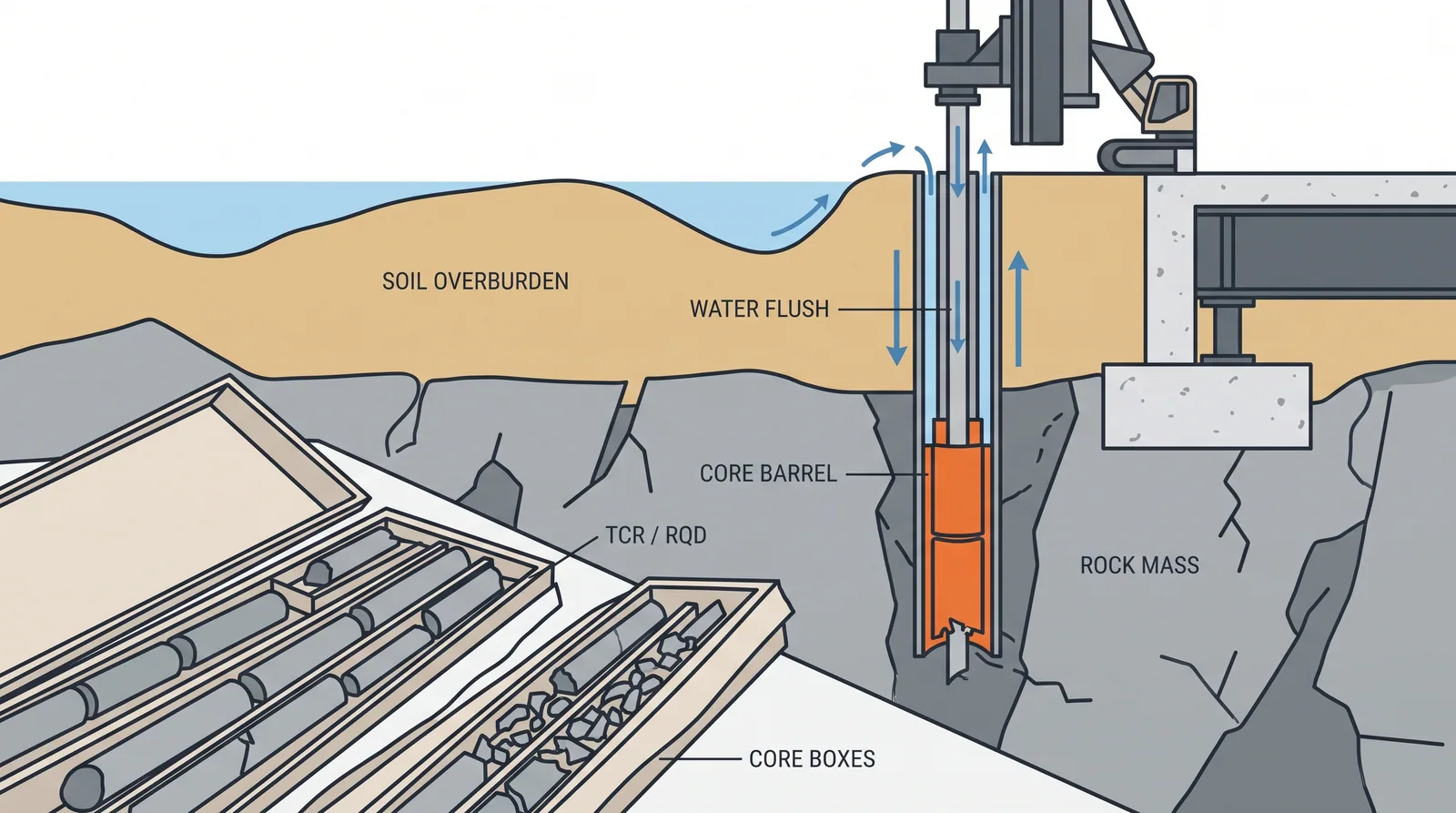
- Change from soil drilling to coring at the first sign of rock (refusal, rock chips, change in drilling rate) and seat casing on the rock head to stop collapse and wash-in.
- Core with double- or triple-tube barrels (HQ3 or PQ3 for weak and fractured rock) using water or polymer flush; keep runs short, 1.5 m or less, in poor rock to protect recovery.
- Core at least 3–5 m into continuous sound rock to rule out boulders, and to 3 socket diameters or 5–10 m below the expected socket base.
- Log each run: total and solid core recovery, RQD, fracture spacing, weathering grade, field strength, discontinuity orientation, aperture, roughness and infill; photograph each box wet and dry.
- Watch flush return, penetration rate and rod drops; sudden flush loss or a free fall of the rods flags open joints, cavities or karst and must be logged with depth.
- Select specimens for unconfined compression (length to diameter 2–3) and point load tests at close spacing; add televiewer logs, packer tests and high-pressure dilatometer tests where joints, permeability or modulus matter.
- Wrap and protect weak rocks (mudstone, chalk, weathered granite) from drying, store cores for the design team, and classify the rock mass (RMR, GSI or Q) for socket and footing design.
Key numbers
- Core diametersNQ 47.6 mm, HQ 63.5 mm, PQ 85.0 mm; triple-tube HQ3 61.1 mm, PQ3 83.0 mm.
- RQD bands (Deere)below 25 % very poor, 25–50 % poor, 50–75 % fair, 75–90 % good, 90–100 % excellent.
- UCS from point loadroughly 20–25 × Is(50) in many rocks; calibrate per rock type, as the factor is lower in weak rock.
- Proving depth3–5 m of continuous sound rock to rule out boulders (Hong Kong practice uses 5 m).
- Output3–10 m per shift depending on rock strength, fracturing and core size.
Where it fits
- All rock-socketed piles, spread footings on rock, pylon foundations.
- Karst regions, where voids must be proven absent below the socket.
Where it does not
- Accepting a single short core in weathered rock as proof of bedrock: weathering profiles are irregular, core more holes rather than deeper ones.
Choosing it
- Core every support where rock will carry a socket or footing: rock quality, not only rock depth, drives the design.
- Extend coverage between cored holes with open-hole probes and drilling-parameter logging, which are much cheaper per metre.
- In deeply weathered profiles (granite, basalt, schist) prefer more, shallower cored holes to a few deep ones, because rock head can vary by metres over a pile group.
- Add televiewer logging where joint orientation matters (pylon foundations near slopes, rock anchors) and oriented core is impractical.
Plant, pace and money
Risks and controls
What goes wrong
- Core loss in weak zones being logged as intact rock.
- Karst cavities between holes.
Quality assurance
Geologist on the rig, recovery and RQD per run, UCS tests at socket level, cavity probing where karst is suspected.
Origins
Diamond core drilling dates from Rodolphe Leschot's drill of the 1860s; Deere introduced RQD in 1964, and Bieniawski's RMR (1973) and Barton's Q-system (1974) turned core logs into rock mass ratings used for design.
Examples
Sandstone and calcarenite in the Gulf, granite and gneiss in Korea; sockets of 1-3 diameters are typical.
Case studies
Related methods
Further reading
ISRM suggested methods · Eurocode 7-2 Annex · FHWA GEC 10 (drilled shafts) · ISRM Suggested Methods for Rock Characterization, Testing and Monitoring · ISO 14689 (identification, description and classification of rock) · Deere (1964) Technical description of rock cores for engineering purposes · Hong Kong GEO, Geoguide 2: Guide to Site Investigation