Also called: temporary support towers, falsework bents, shoring towers
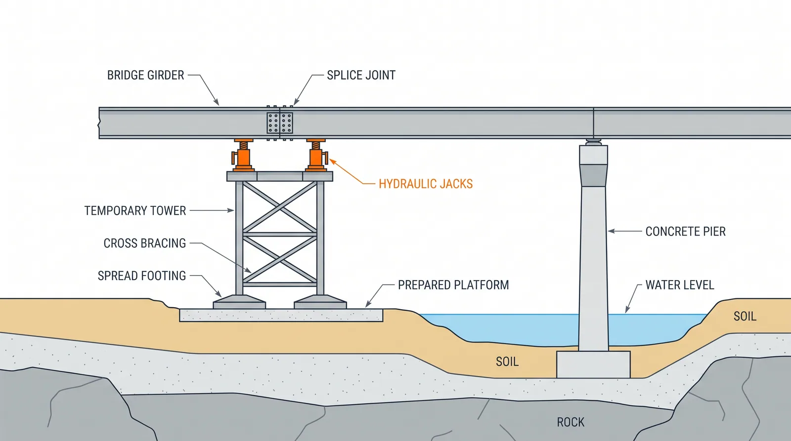
How it is done
- Design the towers as temporary works: reactions from every erection stage, wind on the partly built structure, construction loads, a notional horizontal load and, where traffic passes, impact protection.
- Found the towers on spread footings, mats, piles or the permanent pile caps; verify bearing capacity (plate tests or records) and protect footings from scour, water and undermining.
- Erect the modular towers with plan bracing, tie them to each other or to the permanent piers, and fit adjustable heads (jacks or wedges) and the fixed or sliding pads the analysis assumes.
- Set girder sections on the tower heads at their cambered erection levels, make the splices and bracing, and survey levels after each set.
- Monitor settlement and tower loads (load cells or jack pressures) as the span grows, especially around concrete deck pours.
- Release the towers by jacking down in the analysed sequence, in small steps across all towers, once the span is continuous or the deck has gained strength; check that the girders pick up the load as predicted.
- Dismantle the towers, remove temporary foundations and reinstate the ground or waterway.
Key numbers
- Spacingat field splices, typically 25–45 m apart to match shop piece lengths
- Heightcommonly 10–50 m on land sites; far taller towers have been used for launching (Millau)
- Lateral designwind on the partly built structure plus a notional horizontal load of a few per cent of the vertical load
- Erection-stage windreduced return periods for short exposures (EN 1991-1-6: about 5 years for up to 3 months, 10 years for up to a year)
- CostUSD 50,000–300,000 per tower including foundation (indicative)
Where it fits
- Steel spans over 40-50 m erected by crane, spliced girders, arch rib assembly.
Where it does not
- Deep water, navigation routes, soft ground without piles, positions in the traffic below.
Choosing it
- Choose towers plus crane over a single heavy lift when the ground below is accessible and the crane cannot lift a full span at the required radius.
- Prefer launching or cantilever erection in deep water, navigation channels, high valleys, or where traffic below cannot be protected.
- Prefer a few heavy fabricated towers on piles over many light towers where foundations are expensive (soft ground, water).
- Use the permanent pile caps or pier footings as tower foundations where the layout allows; it saves a temporary foundation and its removal.
Plant, pace and money
Risks and controls
What goes wrong
- Settlement changing the girder geometry, buckling under wind, vehicle impact.
Quality assurance
Temporary works design and check, foundation verification, jack-down sequence.
Origins
Timber falsework and trestles carried early iron spans; modular steel towers took over in the 20th century. The 1958 collapse of the Second Narrows Bridge in Vancouver, caused by an error in the design of a temporary bent, is the classic lesson that temporary supports need the same design rigour and checking as the permanent works.
Examples
The game's spliced girder and steel crane erection assume towers where spans exceed the crane reach.
Case studies
In the bridge game
What Bridge Master applies when you pick it
Deck types: Steel plate girder, Steel box girder, Orthotropic steel box, Steel truss, Steel arch, Network tied arch, Spliced PSC girder. Spans 50-120 m, up to 160 m.
- +35: The standard way to erect steel spans too long for one lift.
- +25: Tied arches and ribs are assembled on bents, then the bents come out.
- +15: Spliced precast girders on towers: the concrete cousin of the same method.
- -25: A single crane lift does it; bents add nothing.
- +10: Bents on spread footings, cranes on the ground.
- -10: Bents on temporary piles from a trestle: fine, slower.
- -35: Bents in deep water are a marine job; launch, float or cantilever instead.
- -30: No bents in the navigation channel: the channel span must be lifted or closed in one piece.
- -25: Bents in the rail corridor only in possessions; usually launch or slide instead.
- -25: Bents over 40 m tall are towers in their own right.
- -40: Bents in the water where in-water works are banned.
- -15: Bents standing through the flood season: debris and scour.
- -10: Long unbraced girders on bents in high wind: tie-downs and bracing sequence matter.
- not allowed: Temporary bents in the water where in-water works are banned.
- not allowed: Temporary bents cannot stand in water; launch, cantilever or float the span instead.
Related methods
Further reading
AASHTO/NSBA Erection Guide · BS 5975 · EN 12812 Falsework: performance requirements and general design · EN 1991-1-6 Actions during execution