Also called: steel launching, incremental launching of steel, push launching
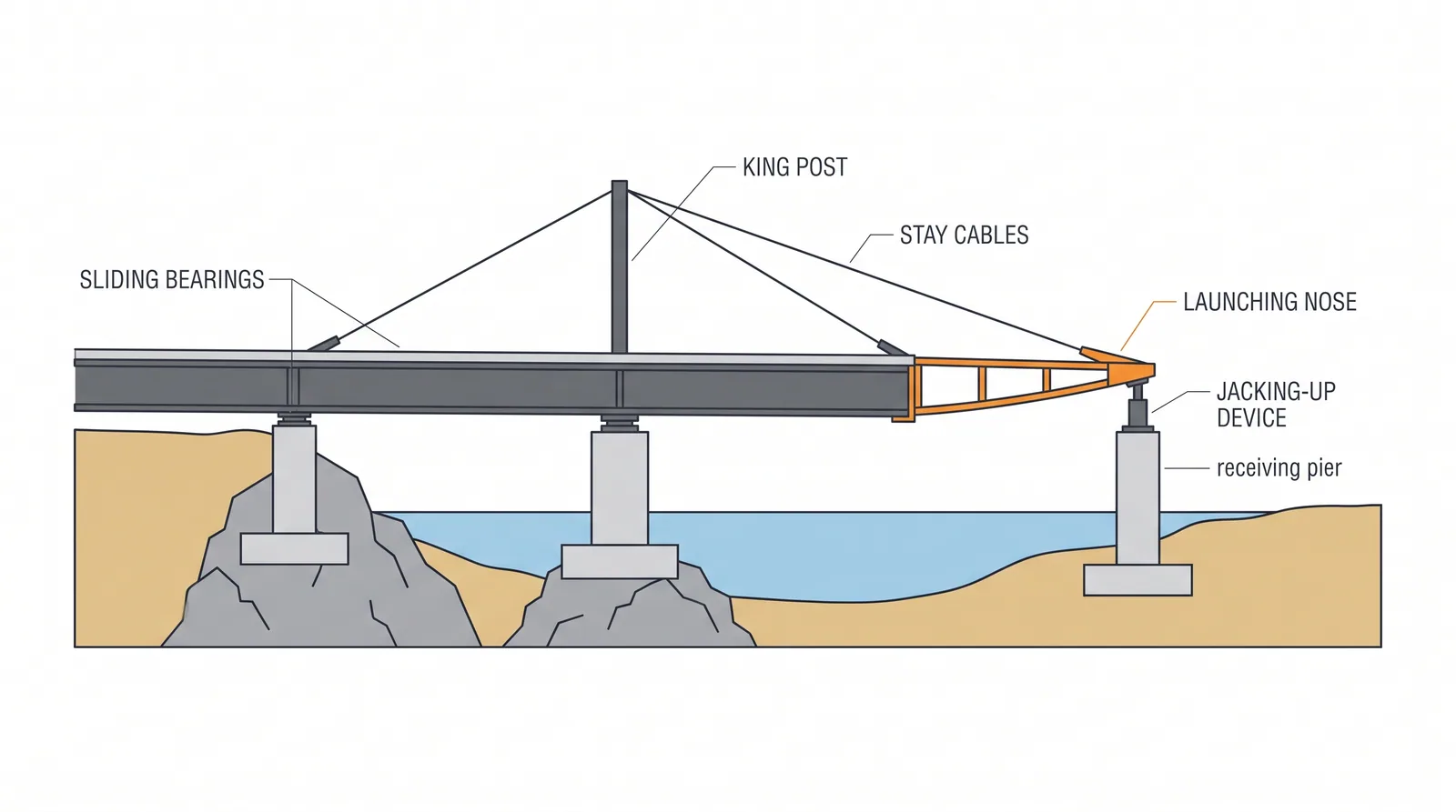
How it is done
- Design the launch: check every girder section for each cantilever and support position, including web patch loading (web crippling) over the launch bearings, and size the launching nose or the king-post and stay system for the longest free cantilever.
- Build the assembly bed behind the abutment on the bridge alignment, usually one to two spans long, with launch bearings or roller boxes at the abutment and on every pier, plus lateral guides.
- Assemble and splice the girders and bracing on the bed; attach the launching nose and, for long spans, a king post with stays to limit the tip deflection.
- Launch in increments with hydraulic push jacks, strand-jack pulling or lift-and-push devices at about 5–15 m per hour, controlling lateral drift and monitoring jack forces, pier-top reactions and tip deflection.
- Recover the nose deflection with a tip jack as it reaches each pier, then add the next girder lengths on the bed and repeat the cycle.
- When the girder is in its final position, jack it down from the launch bearings onto the permanent bearings in synchronised steps and remove the nose, king post and temporary stiffeners.
- Cast or place the deck slab after launching in the analysed sequence (or launch the composite section if the slab was cast on the bed and the analysis allows it).
Key numbers
- Spans launched without temporary piersabout 40–120 m; longer with temporary towers or king-post stays (Millau's 342 m spans were halved to 171 m by temporary towers)
- Launch speedabout 5–15 m per hour; a launch stage usually within one shift
- Friction at the launch bearingsabout 2–6 % of the vertical reaction on PTFE sliding pads, lower on rollers
- Assembly bedone to two spans long behind the abutment
- Geometryconstant girder depth; straight or constant-radius alignment and constant vertical curve
- Erection costUSD 250–500 per tonne (indicative)
Where it fits
- Straight or constant-curvature bridges over rivers, valleys, railways and motorways; spans 40-120 m; sites with room for the assembly bed.
Where it does not
- Variable depth girders, tight curves, sites without the bed length.
Choosing it
- Choose it over crane erection when the ground below is inaccessible or must stay undisturbed (rivers, deep valleys, motorways, railways) and spans are 40–120 m.
- Prefer crane erection when there is ground access, the curvature varies or the girder depth varies; launching demands a constant section and constant curvature.
- Choose it over cantilever erection (fcm_steel) for long multi-span viaducts of repetitive spans; prefer cantilevering for one or two very long spans.
- Prefer concrete launching (ilm) when the deck is a concrete box; a steel girder is lighter, so it needs fewer temporary piers and a lighter nose.
Plant, pace and money
Risks and controls
What goes wrong
- Web crippling at the roller under the cantilever, lateral drift, nose landing, uplift at the rear.
Quality assurance
Web patch loading checks at each launch position, survey of the nose approach, friction monitoring.
Origins
Pushing iron and steel girders across their piers on rollers dates from 19th-century railway building; with hydraulic jacks, PTFE sliding and computer control it became a standard method for steel and composite viaducts, culminating in Millau (2004), whose 36,000 t steel deck was launched from both ends.
Examples
Millau Viaduct (steel deck launched from both sides with a mast), many German and Korean railway bridges.
Case studies
In the bridge game
What Bridge Master applies when you pick it
Deck types: Steel plate girder, Steel box girder, Orthotropic steel box, Steel truss, Steel arch, PSC box (cast in place). Spans 40-120 m, up to 160 m.
- +30: Steel over water, rail or valley: launch it.
- +20: One short possession for the nose passage.
- -40: Cannot launch variable curvature.
- -15: A crane would do it faster.
- -20: Launching past 120 m needs temporary piers or a stayed nose; cantilever erection is the usual answer.
- not allowed: Steel launch on a variable-radius alignment.
Related methods
Further reading
Rosignoli, Bridge Launching · SETRA steel bridge launching guide · Rosignoli, Bridge Launching (2nd ed.) · EN 1993-1-5 Plated structural elements (resistance to transverse forces, patch loading)