How bridges get built · Site investigation and testing · Bi-directional (Osterberg cell) load test
Also called: O-cell test, bi-directional static load test
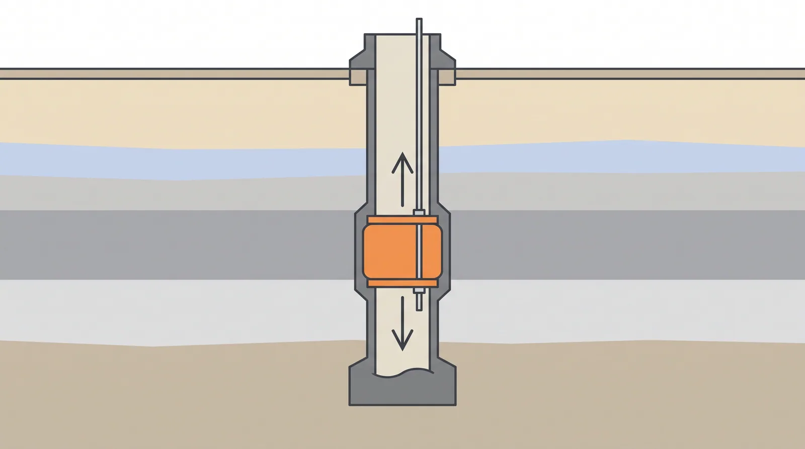
How it is done
- Choose the cell level from the predicted resistance profile so that the shaft resistance above the cell balances the shaft and base resistance below it; use two levels to test base and shaft zones separately.
- Weld the cell assembly between bearing plates into the reinforcement cage; fit hydraulic lines, displacement transducers, telltales and strain gauges at layer boundaries, and pressure-test the lines before lowering.
- Lift and lower the cage with care, as the cell plane is a weak section in handling, and concrete by tremie so that concrete fills around and below the plates.
- When the concrete has gained strength, pressurise the cell in 15–20 increments, holding each for a few minutes and recording cell expansion and upward and downward movement.
- In multi-level tests, load each segment in turn with the other cell left free, so that base and shaft sections are measured separately.
- Construct the equivalent top-down curve by adding upward and downward resistances at equal movement, corrected for elastic shortening.
- Grout the cell and the gap if the pile is to serve as a working pile; report unit shaft resistance per layer and the base response.
Key numbers
- Equivalent top load is about twice the cell load in a balanced test, since the cell loads up and down at once.
- Several cells grouped at one level reach total test loads of 50–300 MN on large shafts.
- Record loadsabout 280 MN on an Incheon Bridge shaft in 2005; more than 300 MN reported since on single piles and barrettes.
- Economic thresholdusually cheaper than a kentledge or reaction-pile test above about 20 MN.
- Test durationone to two days after curing, with a sacrificial cell.
Where it fits
- Bored piles and barrettes above about 1.5 m diameter, pylon foundations, marine piles where reaction systems are impractical.
- Tests to 50-300 MN.
Where it does not
- Driven piles (the cell cannot be cast in); small piles where a conventional test is cheaper.
Choosing it
- Choose a bi-directional test over a top-down test when the load needed is beyond what kentledge or reaction piles can practically supply (roughly 20–30 MN), or when the pile is over water.
- Prefer a top-down test when the behaviour of the pile head matters directly (lateral load, group interaction, downdrag) or the pile is small.
- Use multi-level cells when base and shaft must be separated, or when the expected resistances above and below one level are far from balanced.
- Accept that the test pile is usually sacrificial unless the cell is grouted and the design allows its use as a working pile.
Plant, pace and money
PlantThe cell, hydraulic pump, data logger; no reaction frame.
ProductivityOne to two days of testing after curing; the cell is sacrificial.
CostUSD 100,000-400,000 per test depending on cell size; cheaper than kentledge above about 20 MN.
Risks and controls
What goes wrong
- Cell placed at the wrong level gives an unbalanced test that stops early.
- The tested pile is usually not used as a production pile without grouting the cell.
Quality assurance
Pre-test cage inspection, calibrated cells, strain gauge levels matched to the soil profile.
Origins
Developed by Jorj Osterberg of Northwestern University, who patented the cell in 1987; its first major use was on a large drilled shaft for a bridge near Daytona, Florida, and ASTM issued D8169 for bi-directional static testing in 2018.
Examples
Used on many long-span bridge pylon foundations since the 1990s, including sea crossings in Asia and the Gulf; multi-level cells are now common on piles and barrettes above about 2 m diameter.
Case studies
Incheon BridgeSouth Korea · 2005A bi-directional test on a 3.05 m diameter shaft about 67 m long reached about 280 MN, a record at the time.
Golden Ears BridgeCanada · 2006A two-level test on a 2.5 m bored pile about 74 m long in deltaic sands and clays showed combined resistance above 62 MN, but toe resistance only 37 % of the expected value, which was attributed to debris on the base.
Bridge near Daytona, FloridaUSA · late 1980sFirst major use of the O-cell, on a large drilled shaft, by Schmertmann and Crapps.
Related methods
Static pile load testDrilled shafts (bored piles) with casing or slurryBarrettes and diaphragm-wall foundationsBase and shaft post-grouting of bored piles
Further reading
ASTM D8169 · Osterberg, 1989 onwards