How bridges get built · Piers, pylons and abutments · Seat-type and cantilever abutments
Also called: seat abutment, wall abutment, cantilever abutment
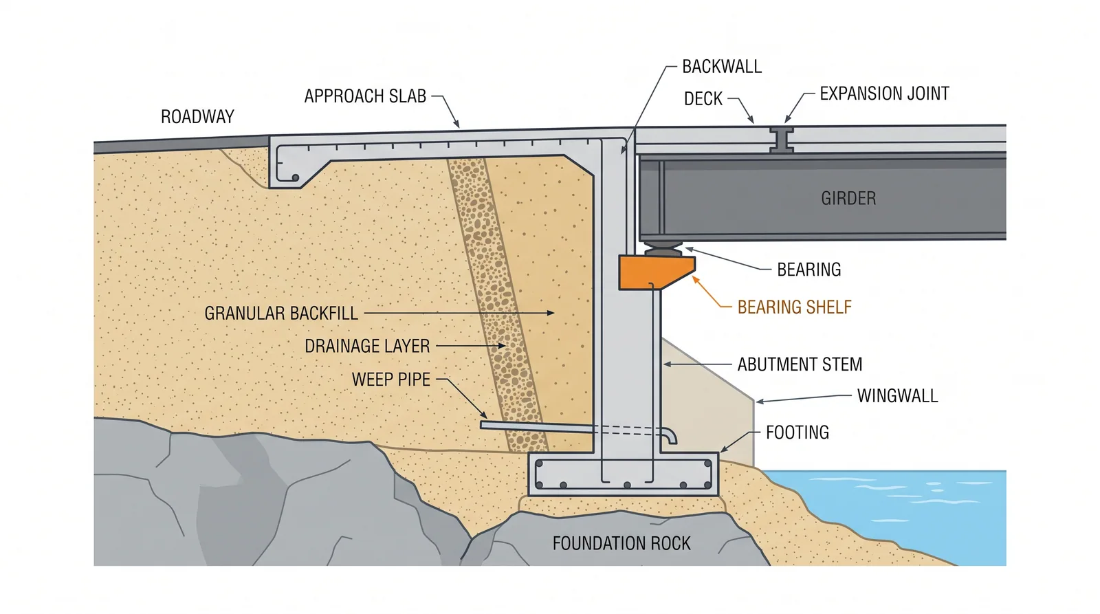
How it is done
- Excavate to formation and confirm bearing, or install piles, then cast the footing or pile cap with starter bars for the stem and wing walls.
- Cast the stem and wing walls in lifts, with weep holes or a drainage pipe at the base and a waterproofing or drainage layer on the back face.
- Cast the bearing shelf with plinths, shear keys and any seismic restrainers, and check the support length against the code minimum.
- Erect the deck on its bearings; cast the backwall (ballast wall) after the girders are placed, so they can be set and the joint gap formed correctly.
- Backfill in compacted layers of 150–250 mm with free-draining granular fill, using only light compaction plant within about 1–2 m of the wall.
- Cast the approach slab on its corbel or seat, and install the expansion joint with the gap preset for the deck temperature at installation.
- Survey wall movement and bearing levels after backfilling and after the deck is complete.
Key numbers
- Stem heighttypically 3–10 m; above about 8–10 m consider counterforts, a spill-through abutment or reinforced soil
- Backfillfree-draining granular fill compacted in 150–250 mm layers to about 95 % of maximum dry density
- Minimum support length (AASHTO LRFD 4.7.4.4)N = (200 + 0.0017L + 0.0067H)(1 + 0.000125S²) mm, taken as 75–150 % of N by seismic zone
- Approach slabcommonly 5–9 m long
- Programme4–8 weeks per abutment
Where it fits
- Bridges over about 60-100 m where thermal movement needs a joint; tall fills; skewed and curved decks.
Where it does not
- Short bridges where an integral abutment removes the joint for nothing.
Choosing it
- Choose a seat abutment over an integral one when the bridge is longer than the integral limit (about 60–150 m depending on authority and material), the skew exceeds about 30°, or the foundation is too stiff to flex.
- Prefer integral or semi-integral abutments for short and medium bridges: no joint, no end bearings and lower whole-life cost.
- Prefer a short seat on an MSE wall, or a spill-through abutment, over a tall cantilever wall when the retained height exceeds about 8–10 m and the ground allows.
- Choose generous seat widths and restrainers in seismic regions: the cost is small next to an unseated span.
Plant, pace and money
PlantFormwork, crane, compaction plant.
ProductivityFour to eight weeks per abutment.
CostUSD 500-800 per m3 of concrete; the wall is often 300-800 m3.
Risks and controls
What goes wrong
- Backfill settlement behind the wall (the bump at the end of the bridge), drainage failure, joint leakage corroding the bearings.
Quality assurance
Compaction tests every layer, drainage inspection, bearing level survey.
Origins
The wall abutment with bearing shelf, backwall and expansion joint has been the default since the early reinforced concrete bridges; the seismic support-length rules followed spans falling from narrow seats in the 1971 San Fernando earthquake.
Examples
Most Korean and Japanese highway bridges; the game's MSE abutment variant puts the seat on a reinforced-soil wall.
Case studies
I-5/SR-14 interchange, San Fernando earthquakeUSA · 1971Spans of the partly built interchange fell from narrow seats; Caltrans then introduced restrainers and minimum seat widths, the basis of today's support-length rules. The rebuilt interchange collapsed again in 1994.
Nishinomiya-ko Bridge approach span, Hanshin ExpresswayJapan · 1995In the Kobe earthquake an approach girder span came off its seat when the supports moved apart, the standard illustration of why seat width matters at every seat-type support.
Related methods
MSE (reinforced soil) abutmentsIntegral and semi-integral abutmentsExpansion jointsBearing installation and setting
Further reading
AASHTO LRFD 11.6 · BS EN 1997-1 · AASHTO LRFD 4.7.4.4 Minimum support length requirements