How bridges get built · Driven piles · Steel H-piles
Also called: HP section piles, bearing piles
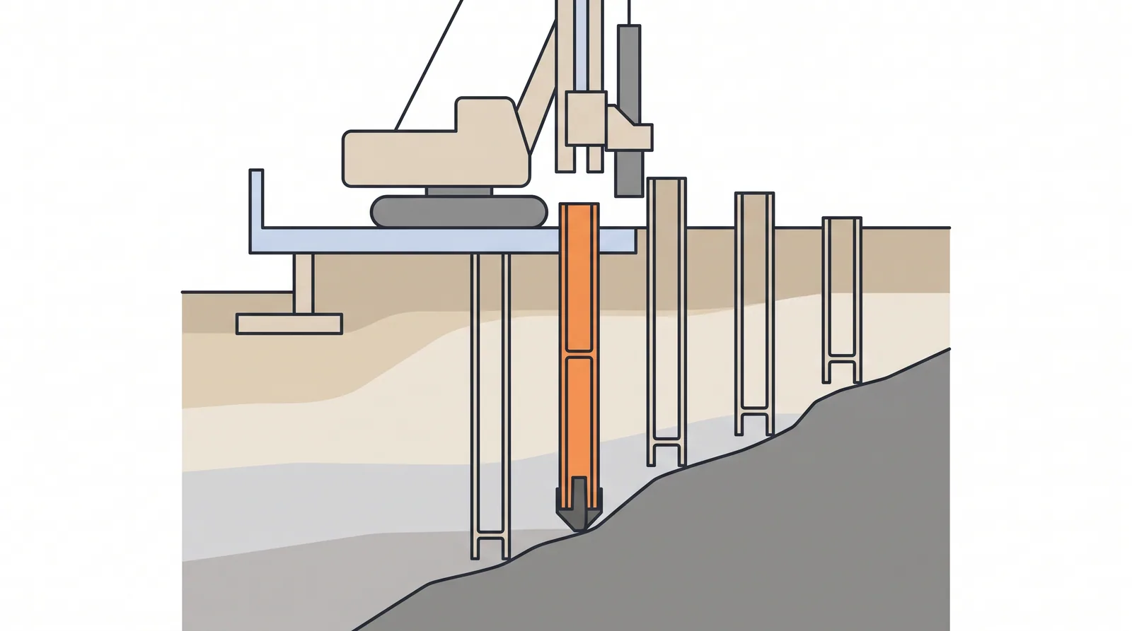
How it is done
- Select section and grade (HP 200-400) for load and driving stress; specify cast-steel driving shoes for gravel, boulders or sloping rock.
- Set the pile in the leads with the flanges oriented as designed (strong or weak axis) and check plumbness or batter.
- Drive with a hydraulic or diesel hammer sized by wave equation; record blows per 250 mm and watch for sudden drops in resistance or rapid drift that point to a bent or damaged toe.
- Splice with full-penetration butt welds or proprietary splicers and inspect before driving resumes.
- Approach the expected rock level with reduced energy, seat the pile and stop at the refusal criterion; never keep driving onto sloping rock.
- Verify capacity by dynamic testing on a sample of piles and restrike piles that rely on setup.
- Cut off square, weld cap plates or shear studs as detailed and embed in the cap; for integral abutments use a single row with the orientation the agency specifies, often in pre-bored holes filled with loose sand at the top.
Key numbers
- SectionsHP 200 to HP 400 (US HP 8 to HP 14 most common, e.g. HP 10x42, HP 12x53, HP 14x73).
- Working loadabout 0.5-2.5 MN per pile.
- Driving stress limit0.9 fy (AASHTO); practical refusal about 10 blows per 25 mm on rock.
- Integral abutmentssingle row, top 2.5-3 m often pre-bored and filled with loose sand to reduce stiffness.
- Corrosion in undisturbed natural soilabout 1.2 mm per 100 years per face (EN 1993-5); more in fills, at the ground-air interface and in the splash zone.
Where it fits
- End-bearing on shallow rock, dense gravels, integral abutments, sites with hard driving where displacement piles would refuse early.
Where it does not
- Deep soft soil with no bearing layer (little shaft resistance); highly corrosive fills.
Choosing it
- Choose H-piles over displacement piles where the pile must pass dense gravel or reach rock: their small displacement lets them penetrate layers that stop pipe and concrete piles.
- Prefer displacement piles (prestressed concrete or closed pipe) where capacity must come from shaft friction in sand or clay: H-piles develop less shaft resistance per tonne of steel.
- For integral abutments, prefer H-piles over concrete and pipe piles: they accept cyclic thermal movement with less cracking at the pile head.
- Prefer drilled shafts or rock sockets on steeply sloping or karstic rock, where H-pile toes skid and bend.
Plant, pace and money
PlantCrawler piling rig, hydraulic or diesel hammer 5-10 t.
Productivity8-20 piles per shift.
CostUSD 120-250 per metre for HP 360.
Risks and controls
What goes wrong
- Tip damage and deflection on sloping rock, corrosion in the splash and ground-air zone.
Quality assurance
Driving points inspected, plumbness, PDA on rock bearing piles.
Origins
H bearing piles followed the rolled wide-flange sections introduced in the United States in the early 20th century; they became the usual end-bearing pile for US highway bridges and later the standard support for integral abutments.
Examples
Integral abutment bridges in the US and UK; many small river bridges in Canada.
Case studies
Happy Hollow Creek Bridge (State Route 50), TennesseeUSA · 1997A 358 m, nine-span jointless precast girder bridge, long the longest fully integral bridge in the US, with stub abutments on a single row of HP 10x42 piles; Tennessee orients the piles for strong-axis bending, whereas many agencies use the weak axis.
Related methods
Integral and semi-integral abutmentsPHC spun concrete pilesDriving control: sets, refusal, restrike and splicing
Further reading
FHWA GEC 12 · AASHTO LRFD 10.7 · Arsoy, Barker and Duncan, Experimental and analytical investigations of the piles and abutments of integral bridges (VTRC, 2002) · Dicleli and Albhaisi, Maximum length of integral bridges based on the performance of steel H-piles at the abutments