Also called: piece-by-piece erection, crane placement of steel, girder erection
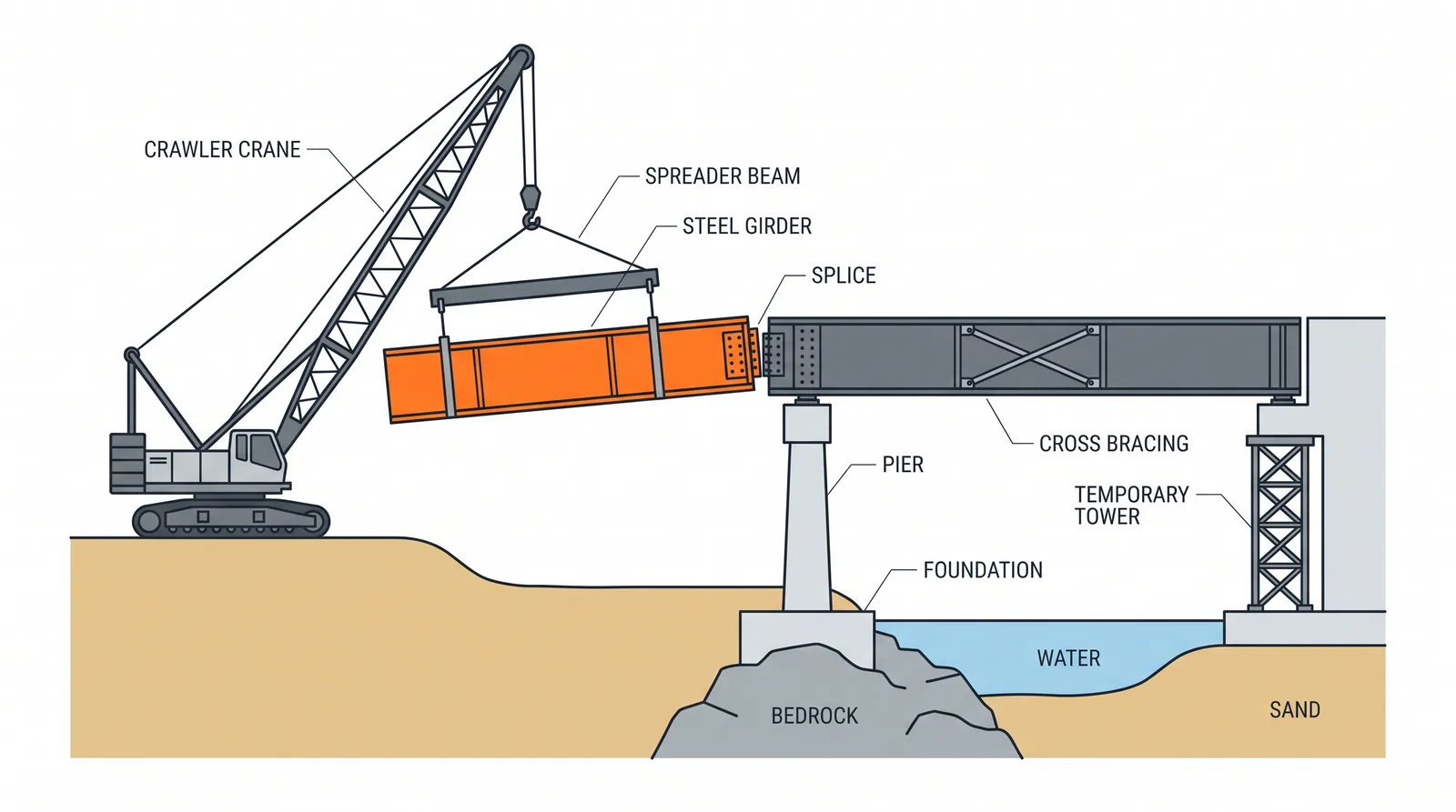
How it is done
- Prepare the erection engineering before any steel arrives: a stage-by-stage stability check of each girder line, a lift plan for every pick (crane, radius, rigging, ground bearing) and the temporary bracing and guying scheme.
- Build crane pads and access, verify ground bearing under crawler tracks or outrigger mats, and stage the girders in erection order with splice plates and bolts at hand.
- Lift the first girder onto the bearings or tower heads and hold it with the crane (or a holding crane) until it is restrained by guys, shoring or a connection to a second girder; a single unbraced girder is the most critical stage of the job.
- Set the next girder and connect the cross-frames or diaphragms before releasing the cranes, so each pair forms a torsionally stable unit; where crane capacity allows, pre-assemble pairs with their bracing on the ground and lift them as one unit.
- Make field splices in the air on temporary towers or with strongbacks, filling about half the holes with drift pins and bolts before the crane lets go of a spliced piece.
- Complete all cross-frames and lateral bracing, check line, level and web plumbness, then tension the bolts in the specified sequence.
- Release the temporary towers once the girders act continuously and place the deck in the analysed pour sequence, monitoring deflections against the predicted camber.
Key numbers
- Span range20–60 m set directly from cranes; to about 90 m with temporary towers or pre-assembled units
- Shop piecestypically 20–40 m long, up to about 45 m and 100 t with road transport permits
- Cranes250–1,200 t crawler or all-terrain; each crane in a tandem lift commonly limited to about 75 % of its chart
- Pacetypically 4–10 girder pieces per shift on a straightforward overpass; one to three days per span
- Erection costUSD 300–600 per tonne (indicative)
Where it fits
- Overpasses, valley bridges with road access, spans 30-90 m, steel arches and trusses assembled on the ground and lifted as units.
Where it does not
- Piers in water without a trestle, unstable single girders left unbraced, heavy units beyond crane charts at the required radius.
Choosing it
- Choose it over launching when there is crane access along the alignment and spans are under about 60–70 m; it needs no assembly bed and copes with curves, skews and variable girder depth.
- Prefer launching (ilm_steel) when the ground below is inaccessible or must stay undisturbed (rivers, deep valleys, railways) and the alignment is straight or of constant curvature.
- Prefer pre-assembled pair or unit lifts over piece-by-piece setting when closures of the road or railway below must be short; the bracing is fitted on the ground.
- Prefer floating-crane or strand-jack lifts of whole spans over water, where the span can be assembled at a quay.
Plant, pace and money
Risks and controls
What goes wrong
- Girder lateral-torsional instability before bracing (several collapses), tandem lift coordination, ground failure under outriggers.
Quality assurance
Erection engineering with stability check at every stage, lift plans, bolt tension inspection.
Origins
Derricks and guy-derricks erected steel girders until mobile and crawler cranes took over after the Second World War. Erection-stage stability is now a formal design check set out in the AASHTO/NSBA Steel Bridge Erection Guide Specification; failures such as the State Route 69 Tennessee River collapse (1995) showed why.
Examples
The game's steel approach spans; most US and European steel overpasses.
Case studies
In the bridge game
What Bridge Master applies when you pick it
Deck types: Steel plate girder, Steel box girder, Steel truss, Orthotropic steel box, Steel arch, PSC I-girder, PSC U-girder, Spliced PSC girder, Network tied arch. Spans 20-60 m, up to 90 m.
- +25: Standard steel erection.
- +20: Light lifts in short windows.
- -35: Use barges or launching.
- -20: Reach limits; launching.
- -20: Over about 60 m a single lift needs a huge crane; use temporary bents.
- -40: Water under the span: a ground crane needs a trestle or crane barges here; launching or a floating crane is the usual answer.
- not allowed: Land crane erection over deep water.
Related methods
Further reading
AASHTO/NSBA Steel Bridge Erection Guide Specification · AISC Steel Construction Manual · AASHTO/NSBA S10.1 Steel Bridge Erection Guide Specification · NCHRP Report 725, Guidelines for Analysis Methods and Construction Engineering of Curved and Skewed Steel Girder Bridges · FHWA, Engineering for Structural Stability in Bridge Construction