How bridges get built · Steel erection · Truss assembly and erection
Also called: truss erection, panel-point erection, truss bridge construction
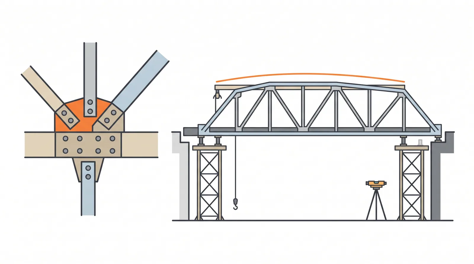
How it is done
- Fabricate members with connection holes drilled to a verified geometry: full or progressive shop trial assembly, or CNC drilling from a checked 3D model, so the panel points close in the field.
- Choose the erection scheme from the site: on falsework towers for short or land spans, by cantilever from the piers with creeper or derrick cranes for long spans, or assembled whole on shore and floated, slid or lifted in.
- Set the bearings and first panels, then erect panel by panel (bottom chord, verticals and diagonals, top chord) so each triangle is closed before the next is started.
- Pin and bolt each panel point to the required fill of drift pins and bolts before load passes through it, and complete lateral and sway bracing as erection proceeds.
- Survey camber, line and panel-point levels at a reference temperature after each stage; correct with jacks at temporary supports rather than by forcing connections.
- Install the floor system (floor beams, stringers or orthotropic deck) and the deck, then release temporary supports in the analysed order.
- Close the last panel or the midspan joint at the planned temperature, tension all bolts and inspect gussets and connections.
Key numbers
- Span rangesimple trusses about 50–150 m; continuous trusses to 400 m (Ikitsuki); cantilever trusses to 549 m (Quebec)
- Truss depthabout span/8 to span/12 for simple spans; shallower ratios for continuous trusses
- Panel lengthtypically 8–15 m
- Paceabout one panel per day on towers; one panel per 2–5 days by cantilever
- CostUSD 4,000–8,000 per tonne fabricated and erected (indicative)
Where it fits
- Rail bridges, long-span river crossings, sites where the deck must be shallow for clearance, floating or sliding in complete trusses.
Where it does not
- Sites without room for assembly or without lifting capacity; highly repetitive short spans where girders are cheaper.
Choosing it
- Choose a truss over plate or box girders for spans beyond about 100–150 m under heavy (railway) loading, or where pieces must be light enough for small cranes and road transport.
- Prefer box girders where fabrication and maintenance cost governs: a truss has many more connections and painted surfaces.
- Erect on towers when the ground is accessible; cantilever when the channel must stay open; assemble ashore and float or slide in when a quay and deep water are available.
- Use a through truss when construction depth below the deck must be small (clearance or approach gradients), and a double-deck truss when road and rail share the crossing.
Plant, pace and money
PlantCranes, derricks, temporary towers, bolting crews.
ProductivityOne panel per day on towers; slower by cantilever.
CostSteel USD 4,000-8,000 per tonne fabricated and erected.
Risks and controls
What goes wrong
- Gusset plate deficiencies (I-35W), member buckling during erection, misfit at closure.
Quality assurance
Shop trial assembly, gusset design check, bolting inspection, survey.
Origins
Truss forms were systematised in the 1840s (Howe, Pratt and Warren patents) and steel trusses dominated long railway spans until the mid-20th century. Lindenthal's Sciotoville Bridge (1917) introduced large continuous trusses; Ikitsuki (1991) holds the record continuous truss span of 400 m.
Examples
Ikitsuki (400 m continuous truss), Japanese and Chinese rail-road trusses, US Mississippi trusses.
Case studies
Sciotoville BridgeUSA · 1917Gustav Lindenthal's two-span continuous railway truss over the Ohio River (two spans of about 236 m), the first large continuous truss.
Astoria–Megler BridgeUSA · 1966376 m continuous truss main span over the Columbia River, the longest continuous truss span in North America.
Ikitsuki BridgeJapan · 1991400 m main span, the longest continuous truss span in the world.
I-35W Mississippi River BridgeUSA · 1967 (collapsed 2007)Deck truss whose U10 gusset plates had been designed about half as thick as needed; with added dead load and construction materials on the deck, they failed. The NTSB investigation led to FHWA guidance on load rating gusset plates.
Related methods
Cantilever erection of steel (derrick and lifting frames)Float-in of complete arches and spansLateral slide (slide-in bridge construction)Repainting steel bridges with containment
Further reading
AASHTO LRFD 6 · NCHRP gusset plate guidance · NTSB Highway Accident Report HAR-08/03 (I-35W collapse) · FHWA, Load Rating Guidance and Examples for Bolted and Riveted Gusset Plates in Truss Bridges