Also called: bridge barriers, crash barriers, parapet construction, slipformed barriers
How it is done
- Select the system from the containment level required by road class, speed, traffic mix and what lies below, and use only a crash-tested system; design the deck edge or cantilever for the barrier impact load.
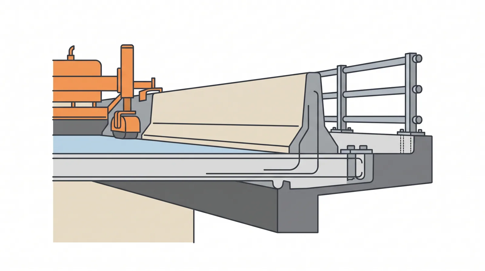
- Cast the deck edge with the barrier starter bars, or with cast-in sockets and anchor bolts set by template to line, level and spacing; check cover and positions before the pour.
- Concrete barriers: slipform from a stringline in one continuous pass, or cast in travelling forms, with contraction joints at regular spacing and full joints at every deck movement joint; cure and seal.
- Steel and aluminium parapets: bolt the posts to the sockets at the specified torque, set rails to line, and provide sliding splices at deck expansion joints.
- Finish the edge: drip groove or drip strip under the cantilever, edge drainage and outlets, cable ducts, lighting columns, noise or wind screens, and protective screens over railways where required.
- Install the transition from the bridge parapet to the approach barrier and the end terminals exactly as tested, with graded stiffness and no snagging points.
- Inspect line and level, test anchor torque or pull-out on a sample, and record the system and its containment level in the bridge file.
Key numbers
- Containment classesEN 1317 N1–N2, H1–H4b, L1–L4; AASHTO MASH TL-1 to TL-6, with TL-4 and TL-5 usual on highway bridges
- Concrete barrier heightabout 810 mm (TL-4 under NCHRP 350), 915 mm (TL-4 under MASH), 1,070 mm (TL-5)
- Design transverse impact force (AASHTO LRFD Table A13.2-1): about 240 kN for TL-4 (raised for MASH) and about 550 kN for TL-5
- Concrete barrier self-weightabout 5–8 kN/m
- Dynamic deflectionessentially zero for rigid concrete barriers; a few hundred millimetres for steel parapets, which sets clearance to columns and screens
- Indicative costUSD 300–800 per m depending on type and containment
Where it fits
- All bridges; containment level by road class.
Where it does not
- Barrier bases without drainage (water sits against the deck edge); untested transitions.
Choosing it
- Choose a concrete barrier over a steel parapet on highway bridges with long runs and heavy trucks: no deflection, little maintenance, fast to slipform; it adds dead load and blocks views and snow clearance.
- Choose steel or aluminium parapets on urban, long-span or weight-sensitive bridges, where appearance, drainage through the edge and quick replacement after impact matter.
- Choose high containment (H4 or TL-5/TL-6) over railways, busy roads and hazardous sites, and on bridges with heavy goods traffic; the deck edge must then be designed for the larger impact load.
Plant, pace and money
Risks and controls
What goes wrong
- Bar anchorage at the deck edge, cracking of slipformed barriers, transitions failing in impact.
Quality assurance
Crash test certificates for the system, anchorage inspection, transition details checked.
Origins
Rigid concrete safety shapes began with the New Jersey barrier in the 1950s, followed by the F-shape and the single-slope barrier from crash testing in the 1970s and 1980s. Acceptance by full-scale crash test moved from NCHRP Report 350 (1993) to MASH (2009) in the United States and to EN 1317 in Europe.
Examples
F-shape and single-slope concrete barriers on highways; steel parapets on urban and rail bridges.
Case studies
Related methods
Further reading
AASHTO MASH · EN 1317 · AASHTO LRFD Section 13 Railings · NCHRP Report 350 · EN 1991-2 (collision forces on vehicle restraint systems) · DMRB CD 377 Requirements for road restraint systems