Also called: main cable erection, deck erection by strand jack, suspension bridge construction
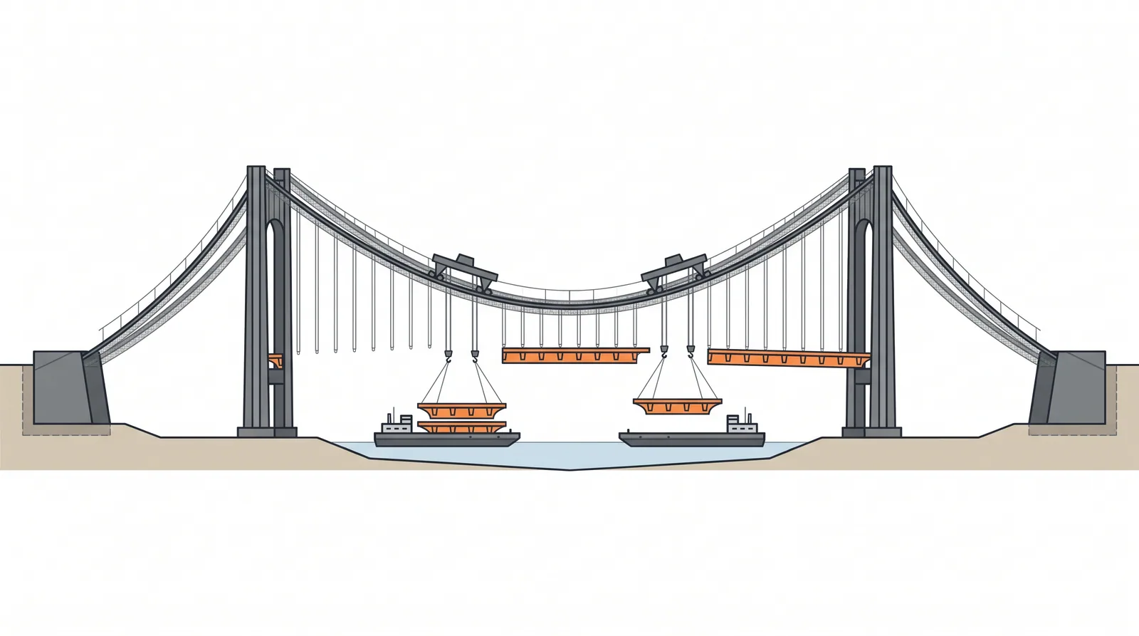
How it is done
- Build the anchorages (gravity, tunnel or rock) and the towers; install the tower saddles, offset toward the side spans by a calculated amount so the free-standing towers are not overstressed as the cables are loaded.
- Cross the pilot rope (by boat, helicopter or drone), haul up the catwalk ropes, hang the catwalks with their cross bridges, and install the hauling system.
- Form the main cables by aerial spinning or PPWS, adjusting each strand to a reference strand at stable night-time temperature; compact the cables and fit cable bands at the hanger points.
- Install the hangers and lift deck sections from barges (or from the deck below) with lifting gantries running on the main cables, usually from midspan toward the towers; join sections with temporary hinges so the deck can follow the changing cable shape.
- Move the tower saddles toward their final position in steps as deck load builds, jacking them on their bases to keep tower bending within limits.
- When all sections are hung and the profile is right, close the temporary hinges by welding or bolting, working out from midspan; install bearings and expansion joints at the towers.
- Wrap and dehumidify the cables, remove the catwalks, install surfacing and monitoring, and record as-built cable and hanger forces.
Key numbers
- Main spanabout 500–2,023 m (record 1915 Çanakkale, 2,023 m)
- Cable sagabout span/9 to span/11
- Wire5–6 mm galvanised, 1,570–1,960 MPa; main cables up to about 1.1–1.3 m diameter
- Hanger spacingabout 12–25 m
- Deck sectionsabout 20–50 m long and 200–1,000 t per lift
- Programmecable formation 3–8 months; deck lifting 3–6 months for a long span
- Deck, cables and towersUSD 10,000–20,000 per m² of main span (indicative)
Where it fits
- Spans over 800-1,000 m, straits and wide rivers, sites where towers can be founded and anchorages built.
Where it does not
- Sites without anchorage geology or space; spans that a cable-stayed bridge can do (they are cheaper below about 1,000 m).
Choosing it
- Choose a suspension bridge over a cable-stayed bridge for spans beyond about 1,100–1,200 m, or where very tall pylons or deep-water pylon foundations make a stayed scheme costlier.
- Lift deck sections from barges where the waterway can be occupied; cantilever small units out from the towers (Akashi Kaikyo) where shipping cannot be obstructed or the water is too shallow for barges.
- Choose a box deck for aerodynamics and weight; choose a truss where a double deck (road and rail) or high torsional stiffness for rail is needed.
- Consider a self-anchored suspension bridge for spans of about 150–400 m where the ground cannot take an earth anchorage, accepting falsework under the deck.
Plant, pace and money
Risks and controls
What goes wrong
- Aerodynamic instability of the partially erected deck (Tacoma is the reminder), cable strand damage, deck section drop, hanger misfit.
Quality assurance
Wind tunnel tests of erection stages, cable survey and sag adjustment, section-by-section geometry, hanger force checks.
Origins
The modern sequence (catwalks, cables formed in place, deck hung from the cables) was set by John A. Roebling and his successors on the Niagara (1855) and Brooklyn (1883) bridges; lifting large prefabricated deck sections from barges became the norm with the streamlined box deck introduced at Severn (1966).
Examples
Akashi Kaikyo (1,991 m), Great Belt, Xihoumen, Yi Sun-sin (1,545 m), 1915 Canakkale (2,023 m).
Case studies
In the bridge game
What Bridge Master applies when you pick it
Deck types: Suspension, Cable-stayed. Spans 700-2000 m, up to 2100 m.
- +30: The only way to build one.
Related methods
Further reading
Gimsing and Georgakis · Honshu-Shikoku Bridge Authority technical reports · Gimsing and Georgakis, Cable Supported Bridges: Concept and Design (3rd ed.)